
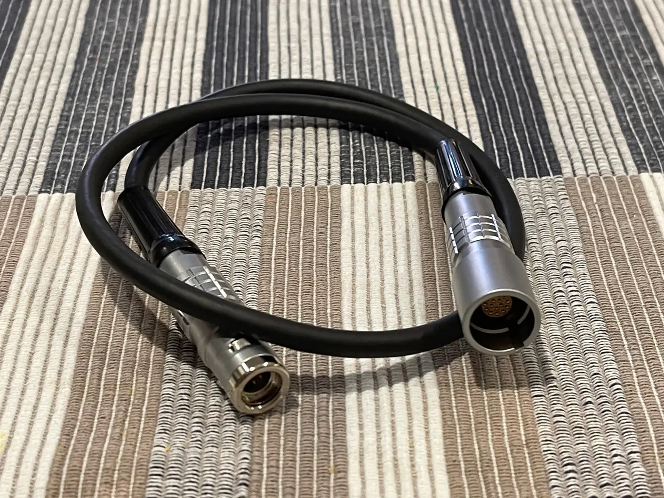

A PAUT setup can be mechanically sound, correctly calibrated and ready to scan, then lose half a shift because the probe will not connect to the instrument. That is why choosing the best cable adapters for PAUT is not a minor purchasing detail. The adapter determines whether a specific probe, wedge and scanner combination can actually be put to work on the job.
For inspection businesses running more than one instrument, probe type or scanning system, adapters are often what keeps equipment productive. The right cable lets existing probes remain useful as fleets change. The wrong one can create channel mapping errors, intermittent signals, poor strain relief or a connection that simply does not fit.
Start with the instrument and probe interface
The first question is not which adapter looks suitable. It is which connector standard sits at each end of the signal path. PAUT instruments, probes and extension cables are available with several connector arrangements, including Hypertronics-style multi-pin interfaces, IPEX-style connectors and manufacturer-specific variants. Similar-looking plugs are not necessarily electrically or mechanically compatible.
Confirm the exact connector on the instrument, the connector on the probe or scanner cable, and the required gender at both ends. Record the instrument model and probe identification rather than relying on memory or a photo taken in poor light. Connector revisions, pin counts and keyed orientations matter.
A useful adapter should preserve the intended connection without forcing an improvised workaround. If a probe cable is under tension, held at an angle or secured with tape to stop it disconnecting, the setup is already telling you it is not fit for regular field use.
Channel count must match the inspection plan
An adapter is only suitable if it supports the channel count required by the probe and focal law. A 16-element probe may appear to connect through a lower-count adapter, but it cannot provide the expected aperture if all element paths are not carried through correctly. The same issue applies to 32, 64 and higher-element arrays.
Check both the number of available transmit-receive channels and the pin allocation. Some applications use every element; others use a restricted aperture or a dual-array arrangement. The adapter needs to suit the actual configuration, not just the highest number printed on the probe label.
For corrosion mapping, this may be relatively straightforward. For encoded weld inspection with multiple groups, a mismatch can be harder to spot until the scan plan is loaded and response quality becomes inconsistent. Confirm compatibility before mobilising, especially where a technician is travelling to a remote site with limited spare equipment.
What the best cable adapters for PAUT need to do
A good adapter has a simple job: transfer each signal path reliably, with the correct mapping, while surviving normal inspection work. In practice, that means more than joining two connector formats.
Signal continuity is the baseline. Every element path needs to be correctly connected from the instrument to the probe, without crossed channels, open circuits or unstable contacts. A channel mapping fault can lead to a misleading beam position, poor focusing or an image that appears plausible but does not represent the weld accurately. That is a quality risk, not merely an inconvenience.
Shielding and connector quality also matter. PAUT signals operate at high sensitivity, and poor connections can introduce noise or intermittent behaviour that is difficult to diagnose on site. An adapter should maintain reliable electrical contact and appropriate shielding through the connection. This is particularly relevant around electrically noisy plant, generators and fabrication areas.
Mechanical durability is equally important. Field adapters are handled repeatedly, packed into cases, dragged across scanner frames and exposed to dust, couplant residue and the occasional hard knock. Look for secure connector engagement, proper strain relief and a cable construction that does not put undue leverage on the instrument port. The most expensive component in the connection path is often the instrument itself.
Choose the adapter type for the way you scan
There is no single best adapter for every PAUT job. The right choice depends on whether the cable is a permanent part of a scanner setup, a short interface between a probe and instrument, or a flexible solution for a mixed probe fleet.
Direct instrument-to-probe adapters
A direct adapter is useful when a probe connector and instrument port use different standards but the cable run is short. It keeps the setup compact and can reduce the number of joins in the signal path. This is often a sensible choice for manual weld work, verification scans or applications where the operator remains close to the instrument.
The trade-off is leverage. A heavy or stiff adapter connected directly to an instrument can place unnecessary load on the port, particularly when the cable is routed poorly. Short adapters should still be supported and routed so the connector is not carrying cable weight.
Extension and break-out configurations
Where the instrument sits on a trolley, at the end of a pipe scanner or clear of the immediate scan area, an extension arrangement may be more practical. It provides working reach and can protect the instrument from water, grinding debris and congested access areas.
The limitation is that every extra connection is another potential fault point. Extension systems need deliberate cable management, protected connector locations and a quick continuity check as part of setup. Do not add length simply because a longer cable is available. Use enough length to work safely without creating loops that catch on scanner frames or foot traffic.
Scanner-specific adapter cables
Encoded scanners may need more than PAUT element connections. Depending on the system, the setup can include encoder leads, probe connections, splitter arrangements or separate interfaces for dual-probe configurations. These jobs benefit from cable assemblies built around the scanner geometry and instrument location rather than a collection of generic leads.
This is where a modular equipment approach pays off. A dedicated scanner with the correct adapter cable can remain ready for a repeat job, instead of being stripped down each time a different configuration is required. PAUT.Tech designs practical scanning hardware around that operational reality: keeping purpose-built equipment available can be more efficient than continually rebuilding one premium system.
Check compatibility before you buy or mobilise
A clear compatibility check prevents most adapter problems. Before ordering or packing, verify the connector type, pin count, element count, instrument model, probe model and intended application. If the arrangement includes a scanner, also check cable exit direction and available clearance around the carriage.
Do not assume that an adapter for one instrument family will suit another version from the same manufacturer. Port layouts and channel capacities can differ. Likewise, a cable advertised for a connector format may have a pin map intended for a different application.
If the supplier provides a wiring or compatibility specification, compare it to your probe and instrument documentation. For critical work, label the adapter with its intended instrument and probe family once it has been verified. A clear label is faster than testing unknown cables at 5:30 am beside a shutdown vessel.
Test adapters as part of normal setup
An adapter should be checked before it becomes the suspected cause of a poor scan. Start with a visual inspection. Look for bent or recessed pins, cracked housings, damaged locking collars, split strain relief and contamination in the connector faces. Couplant and dust can cause trouble when allowed to build up around fine multi-pin connections.
Then connect the complete system and run the checks appropriate to the instrument and procedure. Confirm that all expected elements are detected, the active aperture matches the focal law, and the response from a suitable reference reflector is consistent. A basic element check is useful, but it does not replace a functional scan verification through the whole probe, wedge, cable and adapter assembly.
Watch for faults that appear only when the cable is moved. Intermittent channels can remain hidden while the lead sits still on a bench, then show up as noise or missing response when the scanner starts travelling. Gentle flex testing near strain-relief points can reveal a cable that should be removed from service before it creates avoidable rework.
Avoid false economies
The cheapest adapter is not necessarily the lowest-cost option. A poorly matched or lightly built cable can consume hours in fault-finding, delay a crew and put confidence in the inspection result at risk. That cost quickly exceeds the difference between a generic lead and an adapter selected for the actual instrument and probe arrangement.
At the same time, there is no value in buying a complex, high-channel cable for a simple application that will never use it. Match the adapter to the job, keep verified spares for commonly used configurations, and retire leads that have developed intermittent faults instead of repeatedly sending them back into the field.
The practical goal is straightforward: each probe should connect to the required instrument quickly, carry every required channel correctly and stay reliable through the scan. Get that right, and cable adapters become quiet, dependable parts of the setup rather than the reason a ready-to-go inspection cannot start.