
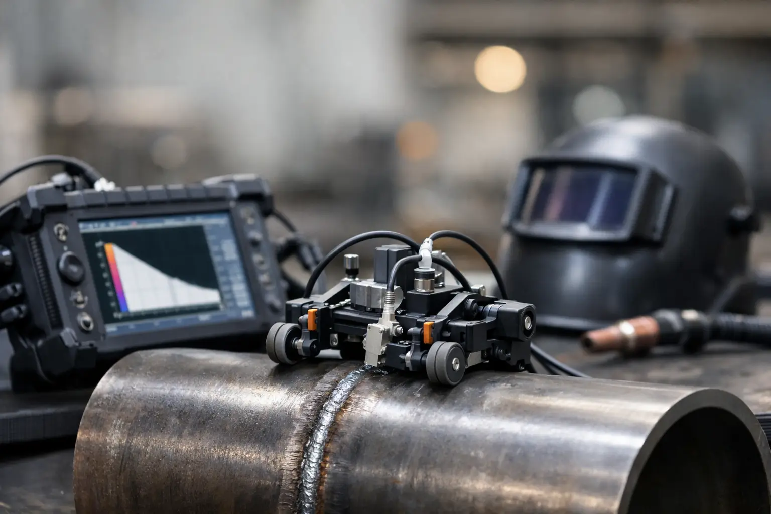

A weld scan can look tidy on the instrument while still being difficult to defend. The usual cause is not the PAUT unit or the analysis software. It is a scanner setup that has been rushed, poorly matched to the weld geometry, or never properly verified. This practical guide to weld scanner setups focuses on the hardware decisions that make encoded PAUT and ToFD data repeatable in the field.
The aim is not to build the most elaborate scanner arrangement possible. It is to establish probe position, scan distance and travel direction with enough control that another technician can reproduce the coverage and the data can be trusted during review.
Start with the inspection objective
Scanner selection begins before probes are fitted. Confirm the weld type, material thickness, access, expected flaw mechanisms and applicable procedure. A butt weld on plate, a circumferential pipe weld and a nozzle attachment may all be inspected with similar instruments, but they place very different demands on the carriage, encoder and probe holders.
For PAUT, the setup must maintain the planned beam path and probe offset throughout the scan. For ToFD, probe centre separation, alignment and stable coupling are especially critical because the lateral wave and backwall response are used to establish position and sizing confidence. Where both techniques are used together, the scanner needs to hold each probe arrangement without one adjustment disturbing the other.
Also decide whether the job needs encoded raster coverage, a single encoded line scan, or manual verification after an encoded pass. More coverage is not automatically better. A broad raster can add inspection time and generate large files without improving probability of detection if the scan plan does not address the likely flaw orientation.
Match the scanner to the surface, not just the probe
A scanner that works well on flat plate can become awkward on a pipe, even where the weld profile appears similar. Surface curvature affects carriage stability, wheel contact, probe pressure and encoded distance. The scanner should be selected around the part geometry first, then configured for the probe arrangement.
On plate, a compact encoded scanner with a stable guide path is often enough for longitudinal and transverse weld coverage. Check that the frame clears the weld cap, any backing bar, attachments and nearby stiffeners. If the scanner rides on wheels close to the weld, confirm that cap reinforcement will not lift one side of the carriage and alter probe contact.
For pipe work, use a scanner intended to track circumference and accommodate the actual outside diameter. The key question is not whether it can physically fit around the pipe. It must maintain consistent travel without slipping, walking sideways or losing probe alignment as it passes the crown and sides. Smaller diameters and restricted access often justify a dedicated pipe scanner rather than modifying a general-purpose frame at the job.
Magnetic attachment can be useful on ferromagnetic components, particularly where overhead or vertical access makes manual restraint impractical. It is not a substitute for checking travel. Scale, coating, weld spatter, surface contour and poor contact can all affect the carriage. On non-magnetic materials, mechanical strapping, chain-style arrangements or guided tracks may be more appropriate.
Build the probe arrangement around reference points
Before mounting probes, establish a clear reference system. Mark the weld centreline where practical, nominate a scan start point and identify the direction of travel. If the procedure uses distance from weld centreline, set that position mechanically and record it. If it uses a datum such as a pipe clock position or component edge, make sure the encoded zero corresponds to that datum.
Probe holders need to control more than probe pressure. They must keep the probe index point, skew and offset stable while the scanner moves. A holder that feels firm when stationary may still flex under drag from couplant hoses or catch on weld dressing. Keep cable and hose routing clear of moving wheels and encoder components, with enough slack for the complete scan but not so much that it pulls the carriage.
For a PAUT setup, verify the probe orientation and wedge direction against the scan plan before calibration. A probe mounted in the wrong direction can still produce a convincing S-scan, particularly on simple reflectors. It will not inspect the intended volume.
For ToFD, measure probe centre separation rather than relying on a marked rail position. Confirm both probes are parallel to the weld, sit evenly on the surface and have comparable coupling. Small changes in separation can alter the time-of-flight geometry used by the procedure and should be treated as a setup change, not a minor adjustment.
Encoder setup is where repeatability is won or lost
An encoder provides position only if it is mechanically coupled to the movement being measured. If the encoder wheel slips, lifts or is driven by a wheel that is not tracking the scan direction, the data position is suspect regardless of the resolution setting.
Set encoder resolution in the instrument according to the encoder specification and confirm the displayed travel against a physical scale. A simple 100 mm check before scanning can expose incorrect counts per millimetre, reversed direction or intermittent encoder response. Repeat the check after moving the scanner to a different surface condition or changing wheel pressure.
The encoder should be located on the axis that matters to the inspection. For a longitudinal weld scan, that is normally travel along the weld. For a raster inspection, distinguish between encoded primary travel and indexed movement. If manual indexing is used, mark each pass carefully and record the increment. If the procedure requires encoded indexing, use hardware that captures it rather than estimating position from paint marks.
Do not assume a higher encoder resolution fixes poor mechanics. Fine sampling on a slipping carriage simply creates finely sampled positional error. Stable wheel contact, controlled travel and a repeatable start reference are more useful than chasing a specification that the field setup cannot support.
A practical guide to weld scanner setup checks
A short setup verification routine saves far more time than re-scanning after data review. It should happen with the full scanner assembled, cables connected and couplant system in the same condition expected during the inspection.
Check the following before the production scan:
- The scanner clears the weld profile and any nearby obstruction across the entire planned path.
- Probe positions, offsets, skew and ToFD separation match the approved scan plan.
- The encoder zero is tied to a known physical datum and displayed travel agrees with a measured distance.
- Coupling remains stable during motion, including over cap transitions, surface changes and the full range of access.
- PAUT sensitivity, wedge delay, velocity and calibration responses are verified using the required reference block or known reflectors.
- The recorded data shows continuous encoder movement with no dropouts, sudden distance jumps or unexplained loss of amplitude.
The last point deserves attention. Watch a short live scan before committing to a long weld. It is easier to find a loose connector, a cable snag or an encoder direction error in the first 200 mm than after a full circumference has been recorded.
Design for field conditions and changeovers
Inspection work rarely happens on clean, open plate at bench height. Heat, wind, limited access, protective coatings, uneven surfaces and awkward weld locations all influence scanner performance. Build enough adjustment into the setup to handle normal field variation, but avoid an arrangement that requires repeated rebuilding between common jobs.
This is where purpose-built, modular hardware can be more practical than one expensive scanner expected to do everything. A dedicated plate scanner, pipe scanner and ToFD arrangement can reduce changeover time and keep a proven configuration intact. For a small inspection business, that can also allow more than one crew to work without waiting for a single scanner to return from another site.
PAUT.Tech approaches scanner hardware from this working reality: fit-for-purpose components that can be configured for the task without treating every inspection as a custom mechanical build. The right balance depends on job volume. A contractor handling occasional varied work may value adaptable accessories, while a team repeatedly inspecting one pipe range gains more from leaving a dedicated setup assembled and verified.
Record the setup so it can be repeated
A defensible scan is easier to support when the setup record is specific. Record scanner type, probe and wedge identification, probe offsets, ToFD separation where used, encoder configuration, scan direction, datum location, index increment and calibration details. Photographs of the assembled scanner and the zero reference are often useful, especially where access is restricted or the geometry is unusual.
Record any departure from the intended plan as well. If a bracket prevented full scanner travel, if a local repair changed the surface condition, or if a section required a different carriage arrangement, capture it while the job is fresh. This gives the data reviewer context and helps the next technician avoid repeating the same problem.
Good weld scanner setups are not defined by how many adjustable parts they contain. They are defined by whether the probe geometry, encoded position and coupling remain controlled from the first millimetre to the last. Set that foundation properly, and the inspection data has a far better chance of answering the question the client actually asked.