
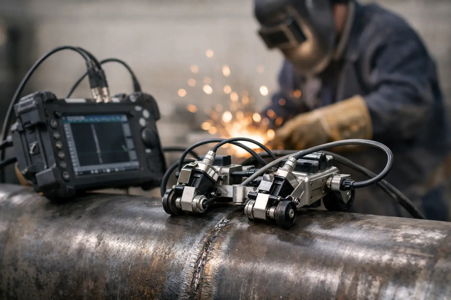

A useful ToFD scanner review should start at the weld, not the catalogue. The question is not whether a scanner has the longest feature list. It is whether it holds the probes in the right position, records trustworthy encoded data, and can be deployed without turning a routine inspection into a rebuild exercise.
For working NDT teams, a ToFD scanner is part of a measurement system. Its performance affects probe separation, index position, scan stability and ultimately the confidence an analyst can have in sizing and locating indications. A scanner that looks tidy on the bench but shifts on a weld cap, loses encoder traction or takes an hour to configure is not helping the job.
What a ToFD Scanner Needs to Do Well
Time of Flight Diffraction relies on consistent geometry. The transmitter and receiver need to maintain their intended probe centre separation, angle and contact while travelling along the weld. When that geometry changes during the scan, the data can become harder to interpret and repeatability suffers.
That makes mechanical control the first thing to assess. The scanner should keep both probes stable through the full scan path, including changes in weld profile, surface condition and orientation. For a manual scanner, smooth travel matters just as much as rigidity. Excessive play in probe holders, loose arms or a carriage that catches on weld reinforcement can introduce unnecessary variation.
Encoder performance is the next practical test. An encoder does not need to be exotic, but it needs dependable contact and a secure mechanical connection. Missed counts, slipping wheels and cable strain create position errors that are difficult to explain after the job. Check how the encoder is mounted, whether the wheel maintains traction on the expected surface, and whether the cable route is protected from being snagged while scanning.
Probe adjustment should be deliberate rather than fiddly. Operators need to set probe centre separation and index distance accurately, then trust those settings to stay put. Clear scale references, positive locking and repeatable adjustment are more valuable in the field than a complicated mechanism with adjustment in every direction.
ToFD Scanner Review: The Field Criteria That Matter
A scanner review is more useful when it reflects the actual jobs being quoted and performed. A narrow plate weld in a workshop has different demands from a circumferential weld on a pipe spool, a corroded surface, or a weld that can only be accessed from an awkward position.
Setup time is a real operating cost
Conventional scanner systems can be capable, but a single high-cost scanner is often expected to cover every application. The result is frequent stripping down, reconfiguration and reassembly between jobs. That time is rarely treated as a direct equipment cost, even though it consumes technician hours and increases the chance that a small part is misplaced or a setting is not checked.
Assess how many steps are required from case to scan. Probe holders, encoder brackets and guide wheels should be simple to fit and remove. It should be obvious which components belong together. If a scanner requires specialised tools, multiple loose fasteners or a detailed setup sequence for every routine weld, it may be better suited to a controlled inspection bay than a busy field programme.
This does not mean every scanner must be universal. In many cases, a purpose-built scanner for a common weld configuration is the more efficient choice. Keeping a dedicated setup ready for plate welds, another for pipe work and another for corrosion mapping can reduce rebuild time and leave more equipment available across the crew.
Fit to the weld profile matters more than appearance
A scanner needs to suit the surface it will run on. Flat plate, small-bore pipe, large-diameter pipe and irregular surfaces all present different guide and stability requirements. There is no single carriage design that is automatically best for all of them.
For weld inspection, look at how the scanner references the parent material rather than the weld crown. A stable reference reduces the chance of the carriage rocking or tracking inconsistently. Consider the available clearance around the weld as well. Nearby nozzles, supports, coatings and limited access can rule out otherwise capable hardware.
The right choice also depends on whether the job requires a one-off encoded scan or repeated production inspection. A flexible adjustable scanner may make sense for varied call-out work. For repetitive weld types, a dedicated scanner can improve consistency and reduce operator fatigue.
Probe holders must protect the scan geometry
Probe holders are often treated as an accessory, but they are central to ToFD data quality. They need to hold the selected probes securely, allow practical adjustment and maintain coupling without placing excessive load on the probe face.
Check compatibility with the probe sizes and frequencies already used by the team. A good scanner should not force the purchase of a completely separate probe inventory for ordinary work. It should also provide enough adjustment range for the required lateral wave, backwall and through-wall coverage, without making the setup vague or difficult to reproduce.
Probe pressure is a trade-off. Too little pressure can affect coupling. Too much can increase friction, wear wedges or make manual travel uneven. The useful design is one that gives the technician controlled contact and keeps that contact consistent over the scan length.
Materials and serviceability count on site
Field equipment gets knocked about. It travels in utes, site boxes and tool cases, gets exposed to couplant, dust and changing weather, and is handled with gloves on. Durability is not simply about making every part heavy. It is about using sensible materials, protected connection points and components that can be replaced without retiring the entire scanner.
3D-printed scanner components can be a practical option where the design is suited to the task and the material is selected for the expected environment. They allow modular designs, application-specific parts and economical replacement of wear items. The limitation is equally practical: printed components should not be assumed to suit every high-temperature, highly abrasive or heavy-load application. Review the material, load path, fastening method and intended duty before assigning the scanner to demanding service.
A modular system has another benefit. If an encoder mount, probe arm or guide component is damaged, the team may only need to replace that part. That can be more sensible than taking an entire premium scanner out of service for a minor failure.
Do Not Buy Features You Will Not Use
It is easy to compare scanner specifications and assume that more adjustment, more attachments and more configurations equal better value. For many owner-operators and smaller NDT contractors, that is not the case. Features that are rarely used still add purchase cost, setup complexity and potential failure points.
Before buying, define the work that generates most of the revenue. Record the common weld geometries, material thickness ranges, access constraints, probe types and encoded scan requirements. Then choose hardware around those jobs first. It is reasonable to maintain a different solution for occasional specialist work rather than burdening every daily setup with capability that is seldom needed.
The same thinking applies to budget. The cheapest scanner is not always economical if it needs constant adjustment or produces inconsistent scan positioning. Equally, the most expensive system is not automatically the lowest-risk option if it becomes a bottleneck because only one unit is available. Multiple fit-for-purpose scanners can increase capacity, reduce rebuild time and spread wear across the equipment fleet.
Questions to Ask Before Committing
Ask the supplier to explain the intended application rather than only the product dimensions. Can the scanner accommodate your current probes and encoder connection? How is probe centre separation set and verified? What is likely to wear first, and can that part be replaced? Is the scanner designed for flat plate, pipe, or both? How does it travel over the weld profiles you encounter most often?
Also consider the inspection procedure. The scanner must support the scan plan, calibration approach and reporting requirements used by your business or client. Hardware cannot compensate for an unsuitable ToFD technique, incorrect probe selection or poor calibration discipline. It should, however, make a sound procedure easier to execute repeatedly.
PAUT.Tech approaches scanner hardware from that practical position: fit-for-purpose tools that let inspection teams keep more than one job-ready setup available, rather than repeatedly rebuilding a single expensive asset.
The best scanner is the one that keeps its geometry, gives reliable encoded position data and is ready when the crew needs it. Choose for the jobs that fill the diary, maintain the equipment properly, and let the technique drive the hardware decision.