
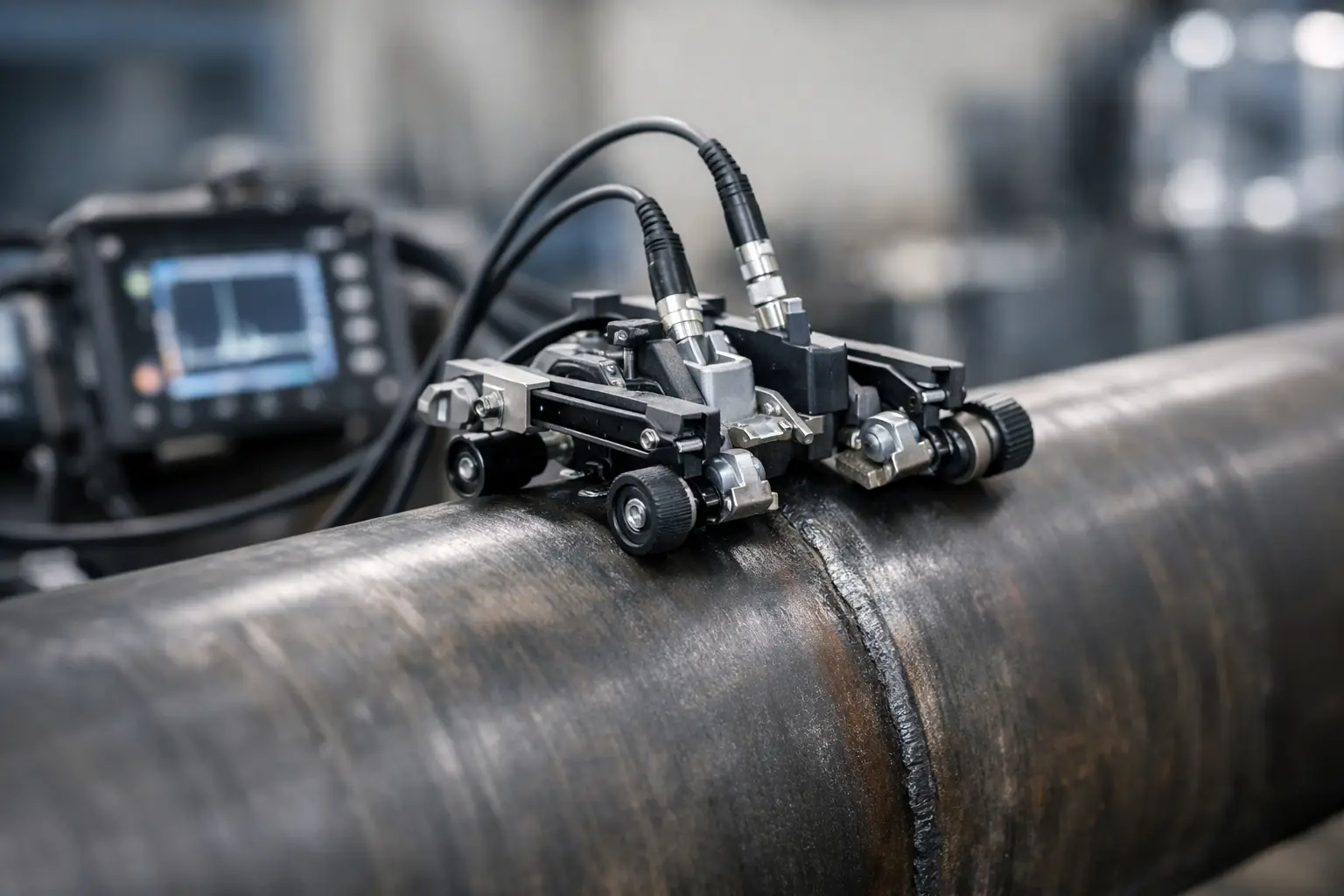

A ToFD setup can look correctly assembled and still produce data that is difficult to interpret. A scanner that rocks on the parent material, drags a probe, loses encoder contact or allows the probe centre distance to move during a scan can compromise lateral accuracy and diffraction response. Knowing how to mount ToFD scanners is therefore less about getting hardware onto a weld and more about controlling the geometry that the inspection relies on.
For field work, the best mounting arrangement is the one that holds the probes at a repeatable stand-off, tracks parallel to the weld centreline and can be fitted without turning every job into a rebuild. The details vary between plate, pipe and restricted-access work, but the mounting principles remain the same.
Start with the inspection geometry
Mounting should follow the approved technique, not the other way around. Before fitting the scanner, confirm the required probe centre separation, probe angle, frequency, element size, refracted mode and scan direction. The probe centre separation is particularly important in ToFD because it determines where the lateral wave, backwall and diffracted signals sit in the image.
Do not use the scanner frame to estimate this dimension by eye. Set the separation from the probe index points using a steel rule, vernier or the adjustment scale supplied with the scanner, then lock the crossbar or probe carriers. Recheck it after tightening. Some clamps pull a carrier slightly as they are tightened, which is enough to alter a carefully set separation.
The frame also needs sufficient travel to keep both probes on sound parent material throughout the scan. If a cap is high, the heat-affected zone is broad, or the weld profile changes around a pipe, check that the wedges will not ride up onto the cap or lose contact near the toes. A nominally correct separation is of limited value if it cannot be maintained over the full scan path.
Prepare the scan path before mounting
A clean, reasonably even track makes scanner setup faster and data more repeatable. Remove loose scale, weld spatter, heavy corrosion products and anything likely to lift a wheel or catch a probe cable. You are not trying to polish the component. You are creating stable running surfaces for the scanner and consistent coupling surfaces for the wedges.
Mark the weld centreline and identify the intended scan start and finish. On long welds, add reference marks at useful intervals so a change in tracking is obvious before it becomes a data issue. For a circumferential weld, confirm the actual pipe outside diameter and look for local ovality, attachments, supports or coating transitions that may affect the scanner’s path.
If the surface is heavily pitted or irregular, a standard wheel-mounted arrangement may not be the best choice. A flexible chain scanner, a wider wheelbase, additional guide wheels or a purpose-built frame may be required. Forcing a rigid scanner over poor surface condition generally creates more uncertainty than it saves in setup time.
Mount the scanner square to the weld
Place the scanner so its travel axis is parallel to the weld centreline. On plate, this normally means the frame runs straight along the weld, with one probe on each side. On pipe, the scanner needs to follow the circumference without walking axially along the pipe.
Start by positioning the probe carriers symmetrically about the weld centreline. Check that each wedge is sitting flat, with its index point at the planned distance from the weld. Then set the guide system so the scanner is constrained by the workpiece, rather than relying on the operator to hold a straight line by hand.
A useful practical check is to move the scanner through a short dry run before coupling. Watch the relationship between the carrier positions and the weld toe. If one side closes in while the other moves away, the scanner is not tracking correctly. Correct the guide position, wheel alignment or chain tension before scanning.
Avoid over-tightening guide wheels or chain systems. Excess preload can increase rolling resistance, distort lightweight frames and create uneven wheel contact. The scanner should be secure enough to resist lateral movement but free enough to travel smoothly at a controlled speed.
Plate and flat welds
For plate work, a wheel-based scanner often provides the simplest arrangement. Set the wheelbase wide enough to resist rocking, especially where the parent material has a slight crown or the scan path passes close to a weld reinforcement. Ensure all running wheels contact the surface. A three-point contact system can be stable, but only if the contact points are correctly set for the surface.
Where the weld is close to an edge, nozzle, stiffener or other obstruction, use a frame that can offset the encoder and probe carriers while preserving the probe geometry. Do not solve an access problem by allowing the scanner to run at an angle to the weld unless that geometry has been considered in the procedure and data interpretation.
Circumferential pipe welds
For pipe, match the scanner to the diameter range and keep the frame centred around the circumference. Chain tension should be even. A chain that is too loose can allow the scanner to drift, while excessive tension can make the unit bind at weld profile changes or local diameter variation.
Check tracking over at least a quarter turn before recording data. Pay attention to the position of both probes relative to the weld toes and to the encoder wheel. On coated pipe, make sure the encoder has enough grip without cutting through soft coating or slipping on a smooth finish. If the surface condition makes wheel encoding unreliable, resolve that before accepting the scan as positionally accurate.
Fit and secure the probes correctly
Install the transmitter and receiver in the correct orientation for the technique. Confirm channel allocation at the instrument rather than assuming the lead labels are right. Reversed probes may still generate an image, but the expected signal order and interpretation convention can be wrong.
Seat each wedge fully in its holder and tighten the clamp evenly. The aim is to prevent movement without crushing a 3D-printed holder, deforming a wedge or introducing a tilt. Check that the probe face is parallel to the inspection surface and that both wedges carry similar contact pressure. Unequal pressure is a common cause of one channel coupling well while the other drops out intermittently.
Route cables so they do not pull on the probe holders or catch on the weld, chain or encoder. Leave enough slack for the full scan length, but not so much that cable loops drag over the scanner. In vertical or overhead positions, cable weight deserves extra attention. A simple strain-relief point on the frame can prevent a good setup from changing as the scan progresses.
Set the encoder as a measurement device
The encoder is not just an accessory that makes the image move. It establishes scan position, sizing reference and data consistency. Mount it where its wheel stays in positive contact with the surface through the full travel range. Check that the wheel turns freely, is not rubbing on a guide or frame member, and is not travelling over a rough weld cap.
Zero the encoder at a known reference point and verify its direction before the production scan. Run the scanner a measured distance and compare the displayed distance with the actual travel. This quick check can expose incorrect encoder resolution, wheel slip or an inverted direction setting.
If the scanner uses a separate encoder wheel, avoid locating it on a different surface condition from the guide wheels. For example, if the frame runs on cleaned steel but the encoder rides on flaky scale, the scanner may physically track well while the recorded position is inaccurate.
Validate the assembly with a short test scan
Before committing to the full weld, apply couplant and run a short encoded scan over representative material. Review the A-scans and image for a clear lateral wave, stable backwall response and consistent coupling from both probes. The exact appearance depends on the component and setup, but sudden amplitude changes, missing backwall, uneven signal quality or repeating position errors should be investigated immediately.
Use the test scan to observe scanner behaviour as well as ultrasonic response. Does it pull to one side? Does a wheel lift at the weld toe? Is the encoder distance stable? Are the cable loops touching the component? These are simple problems to fix before a production scan and frustrating problems to identify afterwards.
Where the procedure requires calibration or sensitivity checks, complete them with the probes mounted in the same configuration used for the examination. Changing probe pressure, separation or wedge orientation after calibration can introduce avoidable variation.
Common mounting mistakes that cost time
Most mounting problems come from treating ToFD as a generic two-probe scan. The scanner may be mechanically sound but still unsuitable for the geometry. Common issues include setting probe separation from wedge edges rather than index points, allowing the frame to track the weld cap instead of the centreline, running an encoder on a slipping surface and using a scanner that is too narrow for the condition of the parent material.
Another frequent issue is trying to make one frame suit every job through repeated adjustment. There is a point where rebuilding a general-purpose scanner costs more time, introduces more wear and creates more setup risk than deploying a dedicated arrangement for plate, pipe or a recurring weld configuration. Practical scanner hardware should reduce that burden, not add to it.
PAUT.Tech designs scanner hardware around that field reality: fit-for-purpose configurations that can be set quickly, checked clearly and kept available for the work they are intended to do.
A well-mounted ToFD scanner should feel uneventful in operation. It tracks straight, maintains coupling, records distance accurately and leaves the operator free to assess data rather than fight the mechanics. That is the standard worth setting before the first production scan starts.