
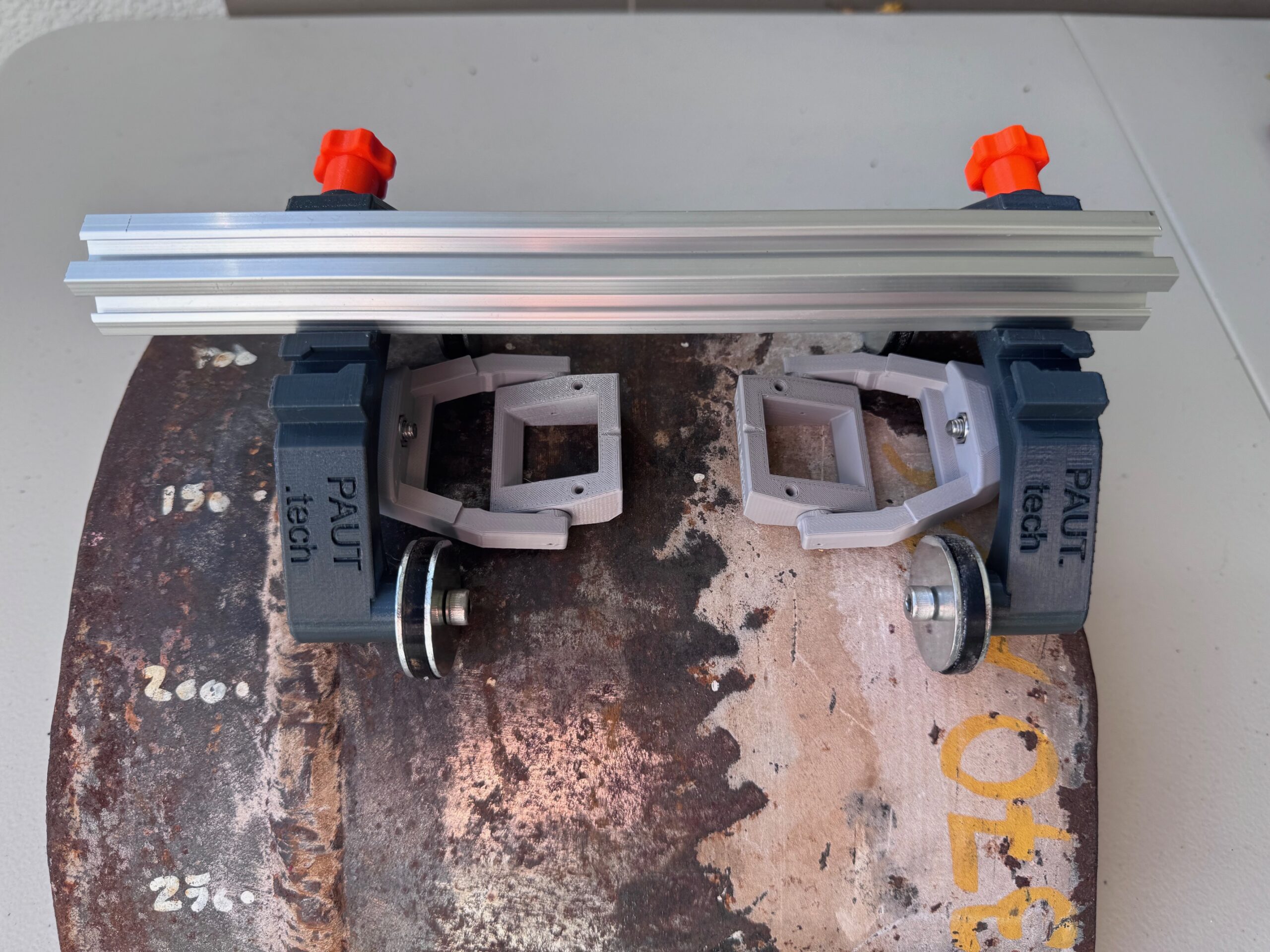

A scanner can look square on the component and still produce suspect data. If it crabs along a weld, if one wheel is carrying more load than the other, or if the encoder is counting movement that the probe is not actually following, the issue starts at the mechanics. Knowing how to align scanner wheels is therefore not a cosmetic setup task. It is part of controlling scan position, probe coupling and encoded data quality.
For PAUT and ToFD work, wheel alignment needs to suit the job rather than an ideal flat test plate. A scanner travelling along a long, straight butt weld needs different checks from one running around pipe, over coating transitions or beside a weld cap. The aim is always the same: predictable travel, consistent probe position and encoder movement that represents real scanner travel.
Start with the scan path, not the adjustment screw
Before touching the wheel mounts, establish the intended scan path. Mark the weld centreline, toe, datum line or inspection band as required by the procedure. On a pipe, confirm whether the scanner is intended to travel circumferentially or axially, then mark a short reference line that gives you something visible to track.
Place the scanner on the component with the probes, wedges and cables installed. This matters. A bare scanner may sit level, then twist once a PAUT probe, ToFD pair, cable bundle or water feed adds side load. Set it up as it will actually be used in the field.
Check that both wheels contact the surface evenly. If one wheel is hovering, lightly loaded or sitting on weld reinforcement while the other is on parent material, adjustment at the axle alone will not solve the problem. You may need a different wheel position, rail spacing, probe holder height or scanner configuration for that geometry.
On a flat plate, a straightedge or marked line is enough to assess travel. On pipe, use the pipe itself as the reference: the scanner should hold a consistent distance from the weld or datum over a complete pass. Do not judge alignment from the first 200 mm only. A small tracking error becomes obvious over a longer run.
How to align scanner wheels step by step
Wheel alignment is best done with small adjustments and repeatable checks. Over-correcting one side usually creates a second problem somewhere else.
Check wheel position and contact
With the scanner resting in its working position, inspect the wheel assemblies from the front and rear. The wheels should sit parallel to each other and square to the intended travel direction. Look for obvious causes of skew first: a bent bracket, loose fastener, debris around an axle, damaged wheel tread or a wheel sitting at a different height.
Rotate each wheel by hand. It should turn freely without a tight point, wobble or excessive side play. A wheel that binds intermittently can pull the scanner off line and cause uneven encoder motion. A wheel with a worn tread can do the same, particularly on coated surfaces or small-diameter pipe.
If the design allows wheel spacing adjustment, set the wheels wide enough to give stable support without creating interference with the weld cap, toes, clamps or adjacent features. Wider spacing generally improves resistance to yaw on a flat surface. On tight geometries, however, excessive width can make the scanner bridge a change in profile or lose consistent contact.
Square the wheel assemblies to the travel direction
Loosen only the fasteners needed to adjust the relevant wheel mount. Keep enough tension on the assembly that it does not move freely while you are checking it. Use the marked scan line, a straightedge or a guide feature on the scanner as a visual reference.
Adjust one wheel assembly in very small increments until the wheels are parallel to the intended direction of travel. Then tighten the fasteners evenly. If the scanner uses independent wheel carriers, confirm both carriers are set to the same orientation rather than correcting one wheel and assuming the opposite side is correct.
On scanners that use a wheelbase or crossbar, measure from a fixed point on the frame to each axle centre. Matching dimensions help, but they are only a starting point. The practical confirmation is how the scanner tracks on the actual component under its working load.
Confirm encoder wheel engagement
An encoder wheel needs consistent contact and enough normal force to avoid slipping, but excessive force can increase drag and wear. Check that its surface is clean and that the tread is not polished smooth, chipped or contaminated with couplant.
Move the scanner slowly along the reference line while watching the encoder response on the instrument. The count should increase smoothly, with no dropouts or sudden jumps. If the encoder count is erratic, do not assume it is an electronics problem. Check the encoder wheel contact, cable strain relief and the mounting bracket before changing instrument settings.
Where the encoder wheel is separate from the main drive wheels, verify it sits on a representative part of the surface. An encoder running across a high weld cap, rough coating edge or irregular corrosion patch may record different travel from the probe path. That difference can distort index position even when the scanner frame appears stable.
Prove tracking before scanning production data
Once the wheels are adjusted, perform a dry tracking pass along the marked path. Watch one fixed point on the scanner, such as the probe holder edge or centreline mark, rather than watching the wheels. If that point drifts away from the reference line, the scanner is still yawing.
Run the scanner forward and back over the same distance. It should return close to its starting line. A minor variation can be normal on rough surfaces, but consistent drift in one direction indicates that the wheel assemblies are not square, wheel loading is uneven, or cable drag is steering the scanner.
For encoded inspection, check distance accuracy over a known length. Mark two points a practical distance apart, travel between them at normal scanning speed and compare the recorded distance with the physical measurement. If the scale is wrong but the travel is stable, encoder calibration may be required. If the scale changes between passes, look for wheel slip, variable contact pressure or debris on the running surface.
A useful field check is to scan a short section twice in the same direction and compare feature position. Then repeat in the reverse direction if the procedure allows. Significant positional movement between passes is a mechanical warning sign. Address it before collecting a full weld record.
Account for cables, probes and surface condition
Scanner wheel alignment can be perfect on an empty frame and poor once cables are involved. PAUT and ToFD cables can exert enough side force to pull a lightweight scanner off track, especially when the cable bundle catches on a weld, support, clamp or the edge of insulation.
Route cables so their weight is supported and their pull is as neutral as possible. During the tracking check, move the cable bundle as it will be moved during inspection. If an assistant will manage cables in production, use the same arrangement during setup. The scanner should not depend on an operator constantly correcting its direction by hand.
Surface condition also sets the practical limit of alignment. Scale, spatter, thick paint edges, pitting and uneven weld caps can steer wheels or reduce encoder traction. Clean a reasonable running path where permitted by the job scope. If cleaning is not possible, slow the scan, shorten the pass length and add verification points rather than forcing a long run with questionable positional control.
On small pipe, wheel alignment is more sensitive because the scanner frame follows a curved surface. Ensure the wheel geometry matches the pipe diameter and that probe holders are not forcing one side of the scanner upward. A configuration that works well on 12-inch pipe may not track acceptably on a much smaller diameter without adjustment.
Common wheel alignment faults and what they indicate
A scanner that consistently walks toward one side usually has a wheel assembly set out of square, unequal wheel loading or cable drag. Start with cable routing, then inspect wheel contact and alignment.
If the scanner runs straight but the encoded distance is inconsistent, focus on the encoder wheel. Slippage, poor contact pressure, tread wear or contamination are more likely than a general frame alignment issue.
If the probe position changes relative to the weld while the wheel path looks stable, inspect the probe holder, wedge mounting and frame flex. The wheels may be correctly aligned while the probe carriage has movement or is being deflected by the component profile.
A scanner that feels stiff or jerky may have excessive preload, damaged bearings, overtightened mounts or wheels fighting each other because they are not parallel. Do not compensate by pushing harder. Extra force increases the chance of probe lift, inconsistent coupling and encoder slip.
Keep alignment checks part of normal setup
Wheel alignment is not a one-time workshop task. Transport, repeated setup, rough surfaces and normal wear can change how a scanner travels. Make a quick tracking check part of each new job configuration, especially after changing probes, wedges, pipe diameter, wheel spacing or encoder position.
Purpose-built scanners reduce the need to repeatedly strip and rebuild one frame for every weld and corrosion job, but every configuration still needs proving on the component. PAUT.Tech equipment is designed around that practical reality: the useful setup is the one that tracks reliably, carries the probes properly and produces data you can defend.
Take the extra few minutes to run a marked-line pass before production scanning. It is far quicker than explaining later why a reported indication position does not match the component.