
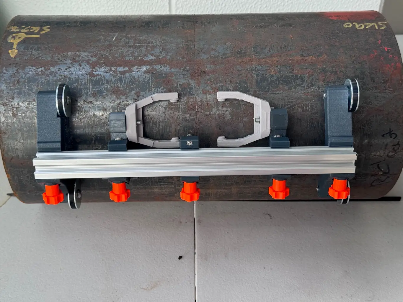

A scanner can be set up correctly, the calibration can be sound, and the scan plan can meet the procedure, yet poor surface prep for ultrasonic weld scanning can still leave you with dropouts, inconsistent coupling and data that takes too long to defend. On field welds, the issue is rarely a perfectly clean laboratory surface. It is usually scale, coating edges, weld spatter, uneven cap profile or access that was not considered before the scanner came out of the case.
Good preparation is not about making every weld look polished. It is about creating a stable, repeatable scanning surface that suits the technique, probe arrangement and encoded scanner being used. The right level of work depends on whether the job is PAUT, ToFD, a combined setup, or a conventional ultrasonic examination with encoded reporting.
What surface preparation must achieve
Surface preparation has three practical jobs: give the probe or wedge reliable acoustic contact, give the scanner a repeatable mechanical path, and remove surface conditions that can create misleading indications or mask real ones.
For contact PAUT, the wedge needs to sit consistently as it travels. A local high spot, sharp spatter bead or thick coating transition can lift one end of the wedge, change the refracted angle response and reduce coupling. The result may appear as a loss of sensitivity, but it is really a changing interface condition.
For ToFD, the probe pair needs consistent separation, contact and alignment on either side of the weld. The technique is particularly sensitive to geometry and lateral position because the lateral wave, backwall signal and diffraction responses are all assessed together. A rough or poorly prepared surface can make it harder to distinguish a genuine response from a coupling-related disturbance.
The scanner also needs a path it can follow without rocking, slipping or climbing over obstacles. This matters where encoded data is being collected. If the mechanical movement is not controlled, the encoder may still record distance, but that distance no longer represents a consistent probe position over the weld.
Start with the scan plan, not the grinder
The common mistake is to prepare the weld before confirming where the probes must run. That can mean unnecessary grinding on the cap while the actual scan surfaces beside the toe remain coated, pitted or inaccessible.
Review the examination procedure and scan plan first. Confirm the weld configuration, material, thickness range, expected inspection coverage, probe arrangement, index offsets and scanner footprint. Mark the weld centreline and identify the travel lanes on both sides of the weld. For a PAUT setup, those lanes may be on one side or both, depending on the coverage requirement. For ToFD, they are generally parallel paths either side of the weld centreline.
Then assess the real condition of the component. Fabricated plate in a workshop, an in-service pipe spool, a painted structural member and a corroded vessel shell all require different decisions. The goal is sufficient preparation for the approved technique, not a one-size-fits-all surface finish.
Remove what affects contact and tracking
Loose rust, mill scale, dirt, dried paint, weld slag and heavy spatter should be removed from the intended probe paths. These conditions interfere with couplant retention and can cause a wedge or probe carriage to ride inconsistently. Pay particular attention to the start and finish of the planned scan, where unprepared material can create an early coupling loss that is mistaken for an equipment issue.
A wire brush, scraper, flap disc or light grinding may be appropriate, provided the work does not alter the weld or parent material beyond what the job allows. Abrasive preparation should leave a reasonably even contact surface without deep grinding marks across the sound path. Coarse grooves can trap air and couplant, while sharp ridges accelerate wedge wear.
Do not grind the weld cap simply because it looks untidy. If the inspection procedure requires the cap profile to remain intact, or if reinforcement height is relevant to the assessment, unnecessary blending creates a separate quality and traceability problem. When cap dressing is required, it should be controlled and agreed before examination, not decided beside the job because the scanner is difficult to run.
Coatings need a similarly practical approach. Thin, well-bonded coatings may be workable with the right couplant and calibration arrangement, but their thickness and consistency matter. Thick coatings, peeling paint and abrupt coating edges are more likely to compromise coupling and probe position. If coating removal is necessary, prepare a strip wide enough for the full scanner travel and any probe index movement, not just the apparent wedge contact width.
Prepare enough width for the scanner
A clean strip that only fits the wedge is often not enough. The scanner frame, wheels, guide arms, encoder wheel and probe holders all need stable contact or clearance. A setup can couple well in a short manual check, then lose repeatability once the scanner begins travelling over an uneven coating boundary or scattered spatter.
Allow for the complete travel lane, including the scanner support points and the full range of probe movement. This is especially relevant on narrow components, near attachments, at pipe supports and close to flange transitions. Before final preparation, place the scanner on the component and move it through the expected scan length by hand. This quick check exposes obstructions, unstable wheel contact and insufficient clearance before couplant is applied.
Where scanning around a pipe, inspect the full circumference that will be covered. Conditions can change substantially between the top, sides and underside of a weld. Gravity, access limitations and previous coating repairs often create different surface conditions around the circumference. A scanner that runs freely at the 12 o'clock position may bind or lose support elsewhere.
Keep weld geometry in the inspection decision
Surface finish is only one part of the problem. Weld geometry affects beam paths, coverage and signal interpretation. High reinforcement, toe blending, mismatch, counterbore transitions and irregular cap shape can all influence what the ultrasonic beam sees.
For PAUT, record any geometry that may affect sensitivity or coverage and make sure the setup reflects the actual component, not an assumed ideal weld. A high cap can restrict wedge placement close to the toe. Excessive mismatch can alter the expected backwall response. If a profile prevents the required coverage, more grinding is not automatically the answer. The correct response may be a revised probe position, a different wedge, a second scan direction or a documented limitation under the governing procedure.
For ToFD, keep the probe paths parallel and maintain the specified probe-centre separation. If the surface contour forces the probes to sit at different heights or angles, the time-of-flight relationships can shift. Check lateral wave continuity and backwall response across representative areas before committing to production scanning.
Verify coupling before collecting data
The final check should happen with the actual probes, wedges, scanner and couplant that will be used for the scan. Do not assume a surface is acceptable because a manual probe produced an echo at one location.
Run the scanner over a representative section and watch the coupling indicators, reference responses and encoded position. Look for gradual sensitivity changes as well as obvious dropouts. A repeated loss at the same location usually points to a surface feature, geometry change or scanner interference. Random losses may indicate couplant supply, cable strain, wedge condition or inconsistent operator handling.
Couplant choice matters. A thin couplant may suit a smooth, flat surface and provide clean scanner movement, while a higher-viscosity product may be needed on vertical, overhead or slightly rough surfaces. Too much couplant can allow a lightweight carriage to float or wander. Too little can starve the wedge during a long scan. Apply enough to maintain a stable film, then check that the scanner remains mechanically controlled.
Calibration and sensitivity checks should be made after the inspection setup is established on the prepared surface. If the surface condition changes during the job, such as a coating edge being crossed or a rough section being encountered, stop and reassess rather than trying to compensate by increasing gain.
Common field problems and practical responses
If the scanner rocks over weld spatter, remove the spatter in the travel path or change the scanner support arrangement if the procedure permits. If the wedge repeatedly loses coupling at a coating edge, extend and blend the prepared strip rather than flooding the area with couplant. If an encoder wheel slips on loose scale or wet coating, clean the travel lane and confirm the wheel has adequate, consistent contact.
When access is the limiting factor, a smaller or more task-specific scanner can be a better answer than forcing a large frame into an unsuitable position. This is where modular hardware earns its keep. PAUT.Tech equipment is designed around practical deployment, allowing inspection teams to configure scanning hardware for the weld, access and technique rather than repeatedly rebuilding one large system for every job.
The preparation work should also be documented when it affects examination conditions. A simple record of coating removal, local dressing, inaccessible areas and any geometry-related limitations gives the data reviewer the context needed to assess the result properly.
A well-prepared surface does not need to be perfect. It needs to let the probes couple consistently, the scanner travel predictably and the encoded data represent the weld that was actually examined. Treat preparation as part of the inspection setup, not a labouring task handed off before the technician arrives, and the scan will be faster to run and easier to trust.