
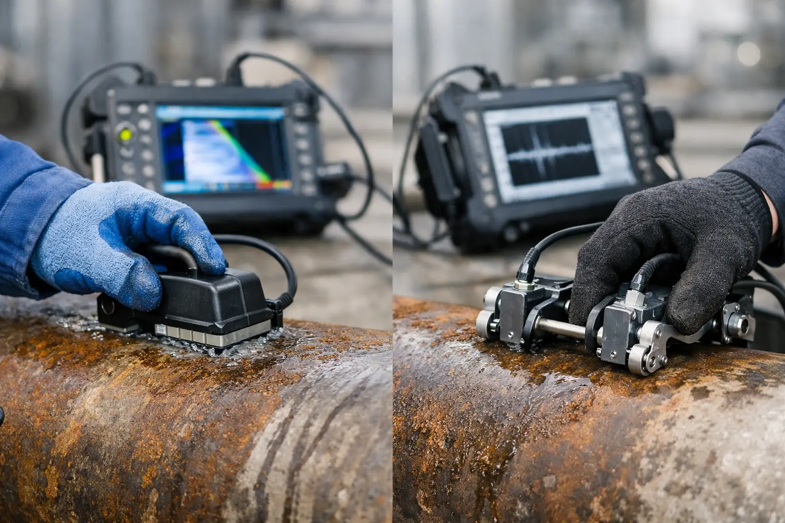

A corrosion job can look straightforward until the reporting requirement arrives. The question is not simply whether to use PAUT or ToFD for corrosion. It is whether the inspection method can reliably show the condition that matters: general thinning, isolated pitting, under-insulation damage, local metal loss near a weld, or a flaw that has developed alongside corrosion.
PAUT and ToFD are both valuable ultrasonic techniques, but they answer different questions. Applying a weld-focused ToFD setup to a corrosion-mapping task can create unnecessary uncertainty. Equally, using a PAUT corrosion scan when the real concern is planar cracking around a weld may leave useful defect-characterisation information on the table.
For most wall-loss assessment work, PAUT is the more practical starting point. ToFD has a place where corrosion and cracking overlap, particularly around welds, but it is rarely the primary method for producing a detailed corrosion map.
What PAUT sees in a corrosion scan
Phased Array Ultrasonic Testing is well suited to corrosion assessment because it can collect encoded thickness data across an area rather than relying on individual spot readings. With the right probe, wedge, scan plan and software setup, PAUT can build a C-scan showing remaining wall thickness, metal-loss distribution and the location of localised attack.
This matters when corrosion is not uniform. A conventional thickness gauge may confirm that a pipe or vessel has lost wall in a particular area, but it can miss the shape and extent of a local pit between measurement points. PAUT gives the inspector a much denser data set. It helps define the lowest remaining wall, the footprint of the affected area and the transition from sound material into corrosion.
For corrosion mapping, the usual approach is a linear scan or electronic raster across the surface. The beam is directed through the remaining wall and the backwall response is used to calculate thickness. Encoded position data ties each thickness value to a location on the component, allowing a repeatable, reviewable map rather than a collection of isolated numbers.
PAUT is particularly useful for:
- general wall thinning over a broad area
- localised pitting and erosion-corrosion
- corrosion adjacent to weld caps, nozzles or attachments
- remaining-wall surveys on pipe, vessels, tanks and structural sections
- repeat inspections where trending is required.
The quality of that map still depends on the inspection setup. Probe frequency, aperture, focal laws, index resolution, scan speed and surface condition all affect the result. A high-resolution scan is useful only if the scanner maintains stable probe contact and the encoder position is trustworthy.
Why ToFD is different
Time of Flight Diffraction works by detecting diffracted ultrasonic energy from the tips of discontinuities. It is exceptionally effective for finding and sizing planar flaws such as cracks, lack of fusion and other weld-related defects. Rather than relying primarily on reflected amplitude, ToFD uses the travel time of diffracted signals to locate flaw extremities.
That strength does not automatically transfer to corrosion. Distributed wall loss and rounded pitting do not always generate the clear, discrete diffraction signals that make ToFD so effective on crack-like defects. A thinning backwall can alter or weaken the backwall signal, but it does not necessarily provide a clean measurement of pit depth, pit profile or remaining-wall contour.
ToFD also has near-surface and backwall dead zones. These can be managed with suitable setup choices and complementary techniques, but they are relevant when corrosion is close to the scanning surface or when only a small amount of material remains. In those cases, relying on ToFD alone can leave uncertainty exactly where the component condition is most critical.
This does not mean ToFD is unsuitable anywhere corrosion exists. It means the technique should be selected for the feature it is designed to assess. If a corroded weld is being examined for cracking, hydrogen damage or fabrication-related planar flaws, ToFD may be an excellent part of the inspection plan. It is simply not the first choice for detailed corrosion mapping.
PAUT or ToFD for corrosion near welds
The decision becomes more nuanced around welds. Weld geometry, cap profile, reinforcement, internal misalignment and heat-affected zones can all complicate a corrosion survey. A simple thickness grid can be difficult to interpret if the backwall response is influenced by geometry rather than actual metal loss.
PAUT offers flexibility here. The inspector can use sectorial coverage, multiple focal laws or a purpose-designed scan path to separate weld geometry from the remaining-wall response. Scans can be taken from the cap, toe or parent material depending on access and the area of concern. For circumferential welds on pipe, a scanner that maintains repeatable probe spacing and encoded travel can make a significant difference to data quality and setup time.
ToFD can complement that PAUT data where there is a legitimate crack concern. For example, corrosion at a weld toe may be associated with fatigue cracking, or internal corrosion may sit near a weld root where service conditions justify a broader integrity assessment. In that case, PAUT can map the wall condition while ToFD is used to examine for planar features. The methods are complementary, not interchangeable.
The key is to avoid treating a combined PAUT and ToFD setup as automatically better. More channels and more data do not improve an inspection unless each data set has a clear purpose, suitable coverage and an acceptance basis.
The practical factors that decide the method
Component geometry is often the first constraint. Flat plate and large-diameter pipe are generally simpler to scan than small-bore pipe, elbows, branches and heavily profiled surfaces. The inspection surface must also be considered. Scale, coating, weld spatter and poor surface preparation can affect coupling and encoder consistency, regardless of technique.
Corrosion morphology is the next factor. Broad, gradual thinning is usually straightforward for PAUT thickness mapping. Isolated sharp pits need sufficient lateral resolution and a scan increment fine enough to avoid scanning over the pit. If the expected pit diameter is smaller than the raster pitch, the inspection may underestimate the local severity. This is a scanning-plan issue, not a software issue.
Access and productivity matter as well. A technician working on a shutdown does not have unlimited time to rebuild one scanner from a straight pipe configuration into a corrosion raster system and then into a weld scanner. Purpose-built, modular hardware reduces that friction. It allows the inspection team to keep a corrosion scanner ready for mapping work while another setup handles weld examination, rather than turning a single premium scanner into the bottleneck for every job.
Reporting requirements should be agreed before the scan begins. Some clients need a minimum remaining-wall value and a defined grid. Others require a full C-scan, dimensions of each reportable indication, repeatable reference positions or data suitable for fitness-for-service assessment. The method, scan resolution and encoder arrangement should be selected to meet that requirement from the outset.
Build the scan around the decision it must support
A useful corrosion inspection does more than produce a coloured thickness map. It needs to support a maintenance or engineering decision. That means the setup must be capable of finding the limiting wall thickness, defining the affected area and providing enough positional confidence for a follow-up inspection or repair.
For PAUT, this usually means selecting a probe and frequency that provide a stable backwall response across the expected thickness range, then setting a practical scan increment for the smallest credible corrosion feature. Calibration should reflect the component and procedure requirements, including velocity, wedge delay, encoder scale and thickness verification on known areas where possible.
For ToFD, the setup should be justified by the expected flaw mechanism. Probe centre separation, refracted angle, material thickness and coverage of the region of interest all need to suit the examination. If the objective is only to determine remaining wall, a dedicated PAUT corrosion approach will usually be faster to deploy and easier to defend in the report.
A practical choice for field inspection
Choose PAUT when the primary question is, “How much wall remains, and where is the loss?” It provides the area coverage, encoded thickness data and visual reporting needed for most corrosion surveys. Use it carefully around complex geometry, and ensure the scan resolution matches the likely corrosion morphology.
Choose ToFD when the primary concern is a planar flaw, particularly in or near a weld. If corrosion is present but cracking is the integrity threat, ToFD may form part of the solution alongside PAUT or conventional UT. Do not expect it to replace a properly configured corrosion map.
The most effective setups are not the ones with the most hardware attached. They are the ones that let the technician arrive at a defensible answer without wasting shutdown time rebuilding equipment, repeating scans or trying to make one technique do a job it was not selected to do.