
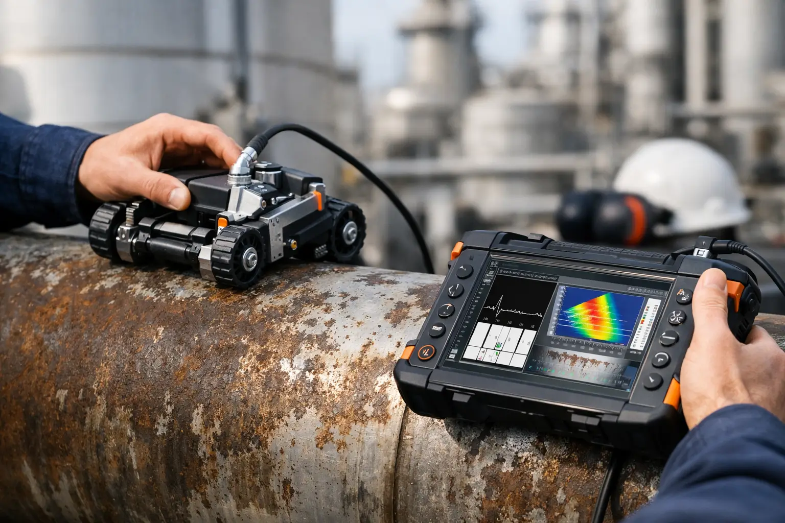

Corrosion jobs usually look simple until the first metre of data comes back patchy, the coating starts fighting the probe, or the scan plan that made sense in the office falls apart on a hot pipe rack. A proper field guide to corrosion scanning has to start there - not with theory, but with the conditions that actually decide whether you get usable wall loss data or waste half a shift chasing setup issues.
Corrosion scanning sits in an awkward space in ultrasonic inspection. It is often treated as lower risk than weld examination, yet poor setup can still produce bad decisions. Miss a localised pit, lose positional accuracy, or apply the wrong resolution to the job, and the result is not just untidy data. It can change repair scope, operating limits, or shutdown planning.
What corrosion scanning is really trying to achieve
At its core, corrosion scanning is not just about finding thin spots. It is about building a reliable thickness picture across an area large enough to support a maintenance decision. That means coverage, repeatability, and confidence in position all matter as much as raw sensitivity.
For that reason, the scanning method has to match the damage mechanism. General wall loss, local pitting, erosion-corrosion, flow-accelerated attack, and corrosion under insulation all behave differently in the data. A fast raster scan that works well on broad internal thinning may not be the right choice where isolated pits are the main concern. The hardware might still move the probe across the surface, but the job requirements are different.
This is where many field issues begin. Teams often start with the scanner they have on hand rather than the scanner that best suits the geometry, access, and expected degradation. That is understandable on a busy site, but it usually costs time later.
The field guide to corrosion scanning starts with geometry
Before couplant, calibration, or scan speed, look at the component like a field operator would. Is it flat plate, small-bore pipe, large-diameter pipe, a nozzle blend, a vessel shell near an obstruction, or a painted section with poor surface access? The geometry determines whether your scanner will track properly, whether the encoder will stay honest, and how much pressure variation the probe will see over the scan.
Flat surfaces are forgiving. Pipes are not. Once curvature tightens, every compromise becomes more obvious - wheel contact, magnetic hold, wedge alignment, probe lift, cable drag, and encoder slip all become part of data quality. Small-bore pipe in particular can expose weak scanner setups very quickly.
Surface condition matters just as much. Scale, coating thickness variation, rough corrosion product, and poor cleaning can all degrade coupling and produce inconsistent readings. There is always a balance here. You do not need to over-prepare every surface, but you do need enough preparation to support the resolution you are trying to achieve. If the goal is high-confidence mapping of localised attack, surface prep standards need to reflect that.
Access usually decides the best setup
On paper, a larger scanner may appear more stable. In the field, it may simply be harder to mount, harder to align, and slower to reposition around clamps, ladders, insulation cutbacks, and nearby steelwork. Compact, task-specific hardware often wins because it lets the operator stay productive in real access conditions.
That is one reason modular scanner ecosystems have become more useful for NDT crews. Instead of forcing one expensive frame into every job, it makes more sense to keep fit-for-purpose options ready for plate, pipe, and awkward access work. The best corrosion setup is often the one that needs the least rebuilding before the scan starts.
Scanner choice affects more than convenience
A corrosion scan is only as good as the mechanical path supporting it. If the scanner cannot maintain stable travel, constant probe contact, and reliable encoder feedback, the ultrasonic side will not save it. Technicians know this, but under schedule pressure it is easy to accept a setup that is merely workable.
That trade-off can be expensive. A scanner that is slightly wrong for the job may still collect data, but it often introduces enough inconsistency to slow analysis or trigger rescan work. On long campaigns, that also means more wear on the hardware and more time spent reconfiguring parts between tasks.
For corrosion mapping, practical scanner selection usually comes down to a few field questions. Will it sit securely on the surface? Can it be deployed quickly by one operator if required? Does it maintain encoder accuracy through the full scan path? Can you keep the probe aligned without constant adjustment? And just as important, can you move from one asset to the next without rebuilding the whole assembly?
If the answer to those questions is no, the setup is already costing more than it appears.
Probe, wedge and scan plan need to work together
The scanning hardware gets a lot of attention, but corrosion work is still a system problem. Probe selection, wedge choice, beam characteristics, scan index, and data resolution all need to line up with the inspection objective.
Where broad screening is the goal, a faster setup with lower spatial resolution may be reasonable. Where you are assessing localised pitting, minimum remaining wall near a support, or a known damage hotspot, higher resolution and tighter index spacing are usually worth the extra time. There is no universal best setting. It depends on whether the client needs rapid area coverage, defect characterisation, or a baseline for future comparison.
This is also where crews can overcomplicate the job. More data is not automatically better data. If the scan is so slow or the file size so heavy that productivity collapses, you may end up covering less area and reducing the overall value of the inspection. Good corrosion scanning is not about chasing maximum settings. It is about selecting settings that answer the maintenance question with enough confidence.
Encoder confidence is non-negotiable
When corrosion maps are used for trending or repair planning, positional accuracy matters. If the encoder slips or skips, the thickness values might still look plausible, but the map becomes less reliable for real-world decision-making. That is especially true when returning to the same area during future outages.
A stable scanner with a dependable encoder setup is therefore not a luxury item. It is part of the measurement chain. If there is any doubt about wheel contact, magnetic hold, or travel consistency, deal with it before you trust the data.
Common field mistakes in corrosion scanning
Most corrosion scanning problems are not dramatic. They are cumulative. Light probe lift on a rough surface, too much cable drag, inconsistent couplant application, rushed indexing, or poor zero reference discipline can all chip away at data quality until the final map is harder to trust.
Another common mistake is treating setup verification as a one-off task. Conditions change during the shift. Surfaces warm up, couplant behaviour changes, operators reposition around obstructions, and scanner components collect grime or wear. A setup that was clean at the start of the morning may not be as clean after lunch.
The better approach is to check performance continuously in small ways. Watch the live response, monitor coupling quality, confirm encoder behaviour, and be prepared to adjust travel speed if the surface condition changes. This is not overcautious. It is normal field discipline.
There is also the reporting side. Corrosion scanning data can look convincing even when the coverage is incomplete or the resolution is poorly matched to the damage mechanism. A good operator stays honest about those limits. If access prevented full coverage, say so. If coating condition affected consistency, note it. Clear limitations are part of a professional result.
A practical field guide to corrosion scanning workflow
The best corrosion workflows are boring in the right way. They are repeatable, easy to deploy, and built around reducing avoidable delays. That usually means selecting hardware that suits the likely job mix, keeping scanner configurations simple, and standardising the mechanical setup wherever possible.
For service companies and owner-operators, this matters commercially as much as technically. If one scanner has to be constantly stripped down and rebuilt between corrosion mapping, weld work, and pipe scans, the equipment becomes a bottleneck. The job might still get done, but productivity drops and hardware strain increases. That is exactly why purpose-built, affordable scanner options have real value in the field. PAUT.Tech has built much of its approach around that practical reality.
Corrosion scanning rarely rewards over-engineering. It rewards equipment that can be deployed quickly, adapted to the surface, and trusted to hold position while the operator focuses on inspection quality. When the hardware supports the task instead of fighting it, the whole job gets easier.
The useful test is simple: if your corrosion scanning setup lets you cover the required area with confidence, without constant adjustment or unnecessary rebuild time, you are probably on the right track. If it does not, the problem is often mechanical before it is ultrasonic.
Good corrosion work comes from respecting the small details early, while they are still easy to fix on the asset instead of later in front of a report.