
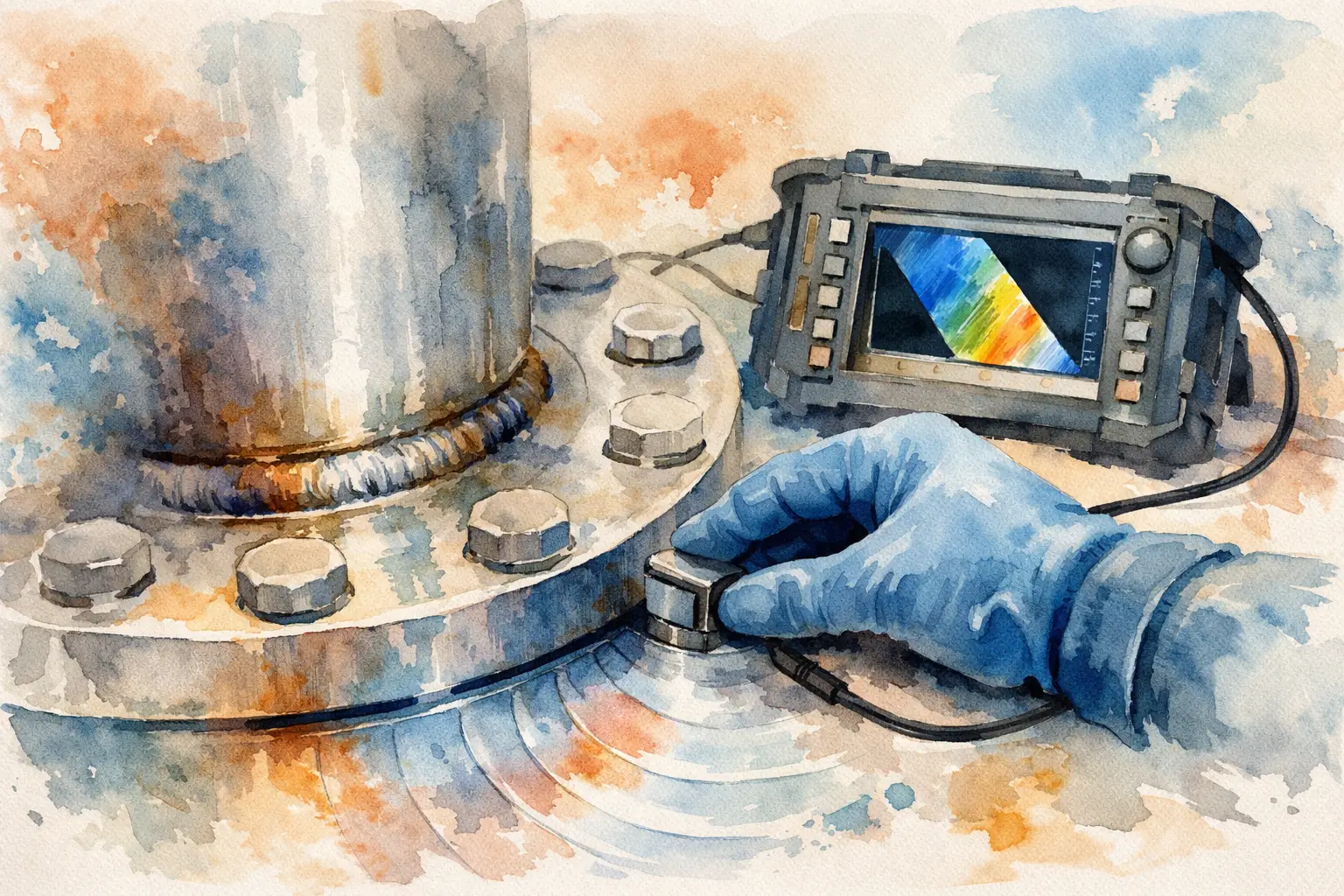

A flange weld can look straightforward until probe access, hub geometry and bolting clearances turn a routine scan into a compromised inspection. Knowing how to inspect flange welds starts with identifying the joint properly, then selecting a method that can interrogate the required volume without creating blind areas or unreliable calls.
For NDT crews, the goal is not simply to collect an A-scan or generate a colourful sectorial image. It is to produce evidence that the weld meets the applicable acceptance criteria, while being clear about what was examined, what could not be examined, and why.
How to inspect flange welds: identify the joint first
“Flange weld” covers several very different configurations. A weld neck flange normally has a circumferential butt weld between the pipe and the flange neck. This is often the most suitable configuration for conventional ultrasonic testing, PAUT or ToFD, provided there is sufficient pipe-side scan length.
Slip-on flanges and socket-weld flanges usually involve fillet welds. These can have an external fillet, an internal fillet, or both. Their geometry makes conventional angle-beam examination more difficult because the sound path encounters multiple reflecting surfaces, including the flange bore, pipe wall and weld faces. A lack of indication does not automatically mean full volumetric coverage.
Before setting up equipment, confirm the flange type, nominal pipe size, wall thickness, material, weld preparation and whether access is available from one or both sides. Check the drawing or weld map where possible. A 150 mm carbon steel weld-neck flange on open pipe is a different job from a corroded socket weld beside a valve body with insulation and limited clearance.
The inspection procedure and governing code should determine the required coverage, technique, scan directions, calibration method and acceptance criteria. Do not build acceptance calls around a generic sensitivity setting when the job requires a qualified procedure.
Start with surface condition and visual examination
Ultrasonic inspection is only as reliable as the contact surface and the information available before scanning. Remove scale, weld spatter, loose coating and rough paint from the scan area. A smooth, clean band on the pipe side is usually preferable to trying to couple directly over an irregular weld cap or close against the flange hub.
Carry out a visual examination before UT. Look for undercut, overlap, excessive reinforcement, arc strikes, surface-breaking cracking, poor tie-in and visible porosity. Check whether the weld profile matches the joint design. If the weld cap is unusually high or the blend into the parent material is abrupt, it may affect wedge travel and make positional encoding less consistent.
Measure the actual wall thickness where corrosion, lining loss or material variation is suspected. Nominal wall is useful for planning, but actual thickness governs sound path, skip distance and focal-law setup. On older process pipework, that difference can be significant.
Build a scan plan around access, not assumptions
For a butt-welded flange, PAUT commonly provides the most practical coverage where there is enough pipe-side room to position a scanner and sweep the beam through the weld volume. A linear array with an appropriate wedge can provide sectorial coverage from the near-side parent material, often avoiding the need to scan over the weld cap.
The scan plan should define probe position, scan direction, index offset, angular range, focal depths and encoded reference points. Establish where the weld centreline sits relative to a repeatable physical feature. The flange face, pipe-to-hub transition or a marked datum can work, but only if it is consistently recorded.
Access often dictates whether one-sided inspection is realistic. A weld neck flange may permit effective coverage from the pipe side, but the far-side fusion face can still be challenging depending on thickness, bevel angle and flange hub profile. Where practical, scan from both sides or use complementary directions to improve confidence in coverage of fusion faces and root areas.
For fillet-welded flanges, consider the likely flaw mechanisms and inspection objective. Surface methods may be more effective for toe cracking. Angle-beam UT can be useful for selected internal discontinuities, but coverage must be demonstrated rather than assumed. PAUT can add valuable imaging and repeatability, yet the geometry may still limit meaningful volumetric examination.
Calibrate on representative material
Use a calibration block and reference reflectors appropriate to the procedure. Material grade, thickness and curvature should be as close to the component as practicable. For small-diameter pipe, a flat block may not represent the coupling and beam behaviour encountered in the field.
Set wedge delay, sensitivity, index point and velocity correctly. Verify the beam profile and focal laws before scanning production welds. If the scan uses encoded PAUT, check encoder direction and distance accuracy with a physical measurement. A reversed encoder or a drifting wheel can make an otherwise good dataset difficult to interpret and report.
Sensitivity should provide suitable response from the reference reflector without saturating the display. Gain alone is not a substitute for a sound setup. Excessive gain increases structural noise and can turn normal geometric responses into apparent indications, particularly around flange hubs and irregular root profiles.
Use PAUT and ToFD for the roles they suit
PAUT is particularly useful when the inspection needs mapped coverage, multiple refracted angles and an image that can be reviewed after the job. A properly configured sectorial scan can help distinguish root geometry, sidewall response and potential planar indications. It also gives the technician a better basis for sizing and locating an indication than a single manual angle-beam trace.
ToFD can complement PAUT on suitable butt welds, especially where detection and through-wall height sizing of planar flaws are required. However, flange geometry can restrict probe-centre separation, access for the probe pair and consistent scanner travel. Near-surface dead zones also need to be considered. ToFD should not be selected by default simply because it is available.
In many flange applications, the practical approach is PAUT as the primary encoded method, supported by conventional UT, ToFD or surface examination where the procedure and geometry justify it. The best method depends on the weld design, expected degradation mechanism, inspection code and available access.
Scan slowly enough to trust the data
Maintain stable coupling and a consistent scanner path. This matters around flange welds because the pipe-to-hub transition can alter contact pressure and make a scanner lift or skew. Watch the live data for coupling loss, unstable backwall response, position jumps and noise changes rather than waiting until review to find a poor scan.
Make more than one pass when the geometry warrants it. A second scan direction, altered index position or different angular range can separate a genuine discontinuity from a geometry echo. Planar lack of fusion may respond strongly from one direction and weakly from another, while a geometric reflector may move or disappear as the beam angle changes.
Do not overcall every response near the root or flange transition. Compare the indication across angles, scan directions and data views. Check its position against the weld profile and expected sound path. A credible report needs evidence that the response is not simply the bore, root face, cap profile or flange hub.
Record limitations as carefully as indications
A useful flange weld report identifies the component, weld number, flange type, material, thickness, method, equipment, calibration details and scan coverage. It should state the applicable procedure and acceptance standard, then clearly describe each reportable indication by location, depth, length, amplitude or sizing result as required.
Just as importantly, document any limitations. Limited pipe-side clearance, inaccessible far-side material, high surface roughness, coating that could not be removed, internal geometry and restricted probe travel all affect coverage. Hiding those limitations creates risk for the client and the inspection provider.
Save the encoded data when PAUT or ToFD is used, along with setup files and relevant calibration records. This gives the client an auditable record and gives your team a defensible basis for review if the weld is repaired, reassessed or compared during a later shutdown.
Choose hardware that matches the job
Flange work is where purpose-built, modular scanning hardware earns its place. A bulky scanner that needs constant rebuilding can turn a short flange inspection into lost time, particularly when crews are moving between butt welds, small-bore pipe and corrosion work in the same shift.
The practical requirement is stable encoded travel, reliable coupling and enough adjustment to suit the pipe diameter and available clearance. PAUT.Tech designs task-specific scanner hardware around those field realities, allowing inspection teams to keep dedicated setups available rather than stripping down one expensive system between jobs.
A good flange inspection is not defined by the number of beams in the focal law. It is defined by a scan plan that suits the joint, data that holds up under review, and a report that tells the asset owner exactly what they can rely on.