
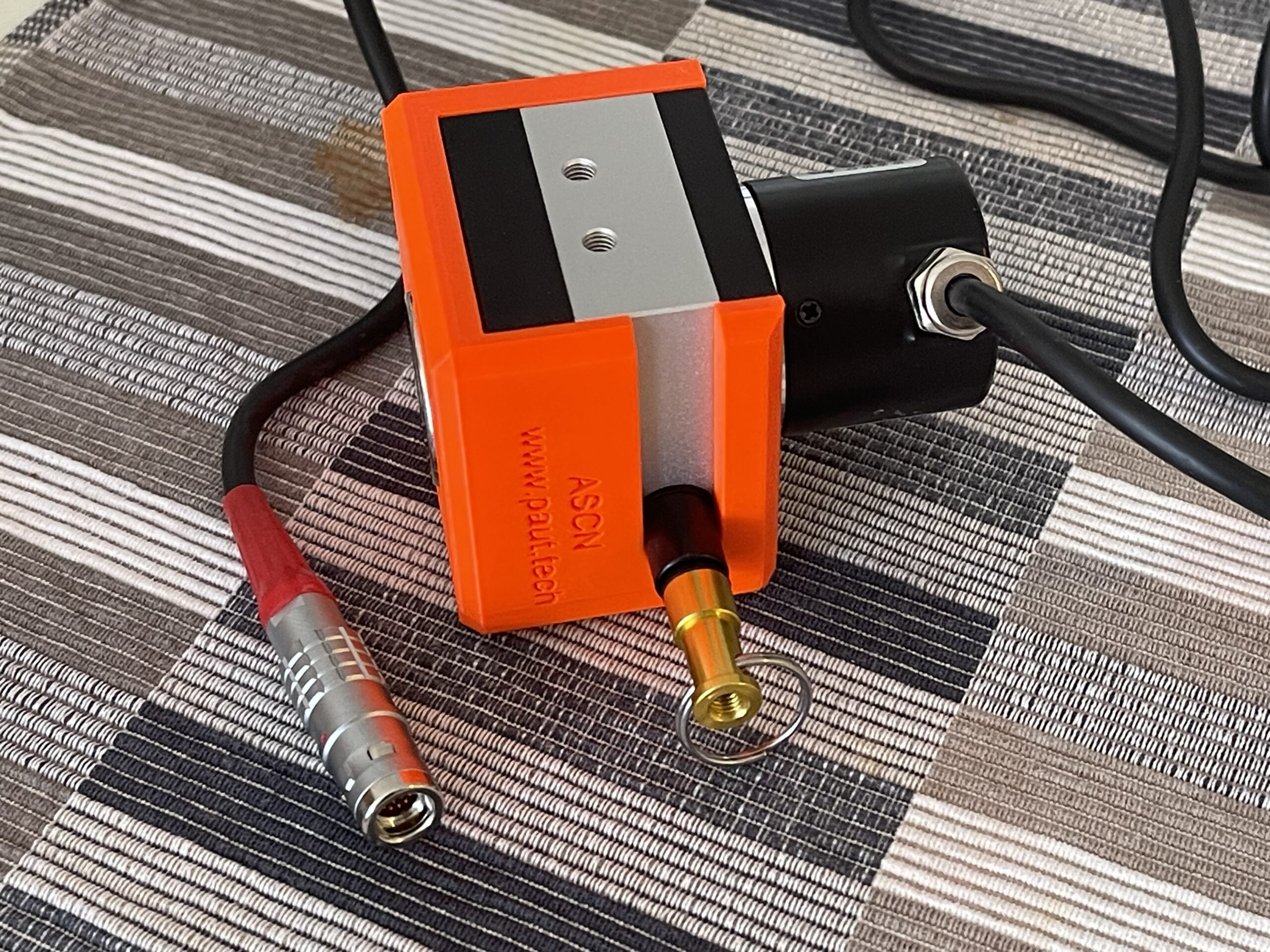

A pipe scan can look acceptable on the instrument while still being difficult to trust later. If the encoder has slipped, been mounted on the wrong reference, or does not match the acquisition setup, position data can be wrong even when the ultrasonic response is clear. This guide to pipe scanner encoders covers the practical decisions that determine whether PAUT and ToFD data is correctly located, repeatable and usable for reporting.
What a pipe scanner encoder actually does
An encoder converts scanner movement into electrical pulses that the ultrasonic instrument records alongside A-scan data. Those pulses become the positional axis of the scan. On a circumferential weld inspection, the encoder tells the instrument where the probe is around the pipe. On an axial corrosion scan, it records travel along the pipe length. With a two-axis scanner, separate encoders define each direction.
That sounds straightforward, but encoder accuracy is not simply a matter of buying the highest pulse count available. The result depends on the complete mechanical chain: the encoder wheel or drive mechanism, scanner frame, pipe surface, mounting position, cable, acquisition instrument and setup parameters. A high-resolution encoder on a wheel that slips on scale or coating will not produce high-resolution position data.
For most field work, the objective is dependable correlation between an indication on the data file and its physical location on the component. This supports accurate sizing, repair marking, rescans and clear communication with the client.
Choosing a pipe scanner encoder for the job
The right encoder is determined by scan direction, pipe condition and the instrument interface. Start with the inspection plan rather than treating the encoder as an interchangeable accessory.
Resolution must suit the scan plan
Encoder resolution is often described as pulses per revolution, or PPR. The usable linear resolution comes from the wheel circumference and the number of pulses counted by the instrument. Quadrature encoders provide two phased signals, commonly called A and B channels, allowing direction detection and, depending on the instrument, multiplication of counts.
More counts per millimetre can improve positional detail, but only to a useful point. If the scan index is 1 mm and the probe footprint is much larger than the calculated encoder resolution, chasing extremely fine encoder counts will not improve the inspection. It may instead make setup more sensitive to incorrect scaling or increase the risk of missed counts when cable and input settings are poorly matched.
Select a resolution that gives enough positional precision for the acceptance criteria, the expected flaw dimensions and the reporting requirement. Weld inspection generally needs reliable circumferential location and sufficient resolution to correlate indications with physical references. Corrosion mapping may place greater emphasis on consistent axial and circumferential coverage across a larger area.
Wheel contact and drive method matter more than specifications on paper
A friction wheel is simple and effective on a clean, reasonably consistent pipe surface. It can be the practical choice for many fabrication and maintenance jobs because it is quick to deploy and easy to inspect. Its limitation is obvious: poor contact creates slip.
Scale, heavy paint, wet surfaces, weld spatter, local pitting and ovality all affect traction. A wheel also needs to be positioned so scanner movement genuinely represents probe movement. If it rides over a changing surface while the probe carriage follows a different path, the displayed position may drift from the actual probe position.
Chain-driven or mechanically coupled encoder arrangements can offer a more positive relationship to circumferential travel, particularly where long scans or repeatability around the full circumference are required. They take longer to fit and need sensible tensioning. Over-tightening a chain can make travel stiff and load the scanner; under-tensioning can introduce backlash and inconsistent movement.
Match the encoder to the pipe range
Pipe outside diameter changes the scanner geometry, wheel contact angle and distance travelled per rotation. A scanner intended for a narrow diameter range can keep the encoder in a predictable position. A highly adjustable scanner covers more jobs, but needs more attention during setup to ensure the encoder remains loaded correctly and the probe stays on the intended scan path.
For contractors covering mixed fabrication work, separate purpose-built scanner arrangements can be more productive than repeatedly rebuilding one universal frame. The saving is not only setup time. It reduces opportunities for incorrect alignment, missing hardware and worn parts being carried from one application to another.
Encoder interfaces and instrument compatibility
An encoder that physically fits the scanner is only half the requirement. It must also communicate correctly with the acquisition instrument. Confirm the connector type, pin-out, supply voltage, output type and the instrument's supported encoder input before mobilisation.
Incremental quadrature encoders are common in PAUT and ToFD scanning. They provide direction and movement information but do not retain an absolute physical position after power is removed. This is normal for most scanner applications, provided a clear start reference is established for each scan.
Some encoders include an index pulse, usually one pulse per revolution. This can be useful as a repeatable reference point, but it is not a replacement for a practical scan datum. On a pipe weld, mark the zero position on the component and ensure the scan plan, instrument setup and report all use the same reference convention.
Cable selection also deserves attention. Encoder signals are low-level control signals and can be affected by damaged connectors, strained cable glands and poor routing around moving scanner parts. Keep the cable clear of wheels, chains and sharp weld caps. Before scanning, manually move the scanner in both directions and confirm the instrument display increments and decrements as expected.
Setting encoder scale without introducing error
The instrument needs to know how many encoder counts equal a millimetre, or how many counts equal one circuit of the pipe. This scaling is where otherwise sound hardware can be undermined.
Do not rely only on a nominal wheel diameter or a value from a previous setup. Measure or verify movement against a known distance where possible. For circumferential scans, confirm the programmed travel corresponds to the actual pipe circumference or the intended scan length. On pipes with coatings, weld caps or irregular surfaces, validate the scale in the same area and condition where the scan will occur.
There are four checks worth making before committing to production data:
- Confirm the encoder direction matches the displayed scan direction.
- Verify the measured travel against a marked physical distance.
- Check that the start position is repeatable after removing and refitting the scanner.
- Watch for count loss or erratic movement while passing the weld cap, support points or rough surface areas.
These checks take minutes. Re-inspecting a completed weld because a positional axis is wrong takes far longer and can create an avoidable reporting problem.
Common field faults and what they usually mean
A scan that stretches or compresses relative to the actual component length usually points to incorrect encoder scaling or consistent wheel slip. Compare a known marked distance with the displayed distance first. If scaling is correct but the error appears only in certain areas, inspect wheel contact and scanner loading.
A position trace that jumps or drops out is often caused by cable damage, a loose connector or an encoder wheel intermittently losing contact. Start with the simple mechanical checks. Field equipment spends time in dust, moisture, grinding debris and transport cases, so connector condition and cable strain relief are not minor details.
If movement is recorded in the wrong direction, swap the configured direction in the instrument or correct the channel assignment according to the equipment documentation. Do not work around it by mentally reversing locations during interpretation. That creates unnecessary risk once multiple scans and reporting references are involved.
Backlash is another issue on scanners that reverse direction. It can appear as a short section of apparent movement before the encoder properly responds after a direction change. Keep drive elements tensioned appropriately, minimise unnecessary reversals and use a scan pattern that suits the scanner's mechanical behaviour.
Building an encoder setup that stays practical
The best arrangement is not necessarily the most elaborate. It is the one technicians can fit consistently, verify quickly and trust through a shift. For a small NDT team, that often means keeping scanner and encoder combinations dedicated to common work: one for a regular pipe diameter range, another for corrosion mapping, and a separate configuration for specialised weld geometry.
PAUT.Tech takes this practical approach by providing modular scanner hardware intended to be configured around the job rather than forcing every inspection through one expensive, frequently rebuilt system. The value is in having hardware available when the work arrives, with less rebuild time and less strain on a single scanner.
Treat encoder setup as part of the inspection procedure, not an accessory check. A clean reference mark, verified scale and stable mechanical contact give the operator confidence that every indication can be found again when it matters.