
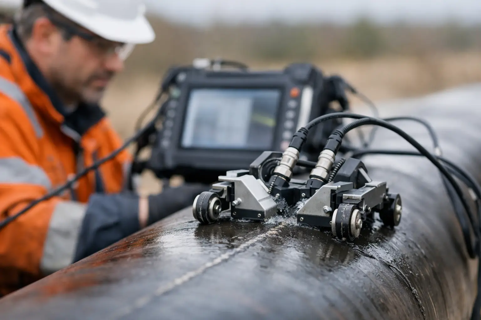

A ToFD setup can have the correct probes, calibrated gain and a sound scan plan, then still produce a poor image because the acoustic path into the component is inconsistent. Knowing how to improve ToFD coupling is less about adding more gel and more about controlling the whole contact system: surface, wedges, probe pressure, couplant delivery and scanner travel.
For working inspection teams, stable coupling protects more than image quality. It reduces rescans, makes sizing calls more defensible and prevents a small scanner issue from becoming a costly hold point on site.
How to improve ToFD coupling before scanning
Start with the surface, not the instrument. ToFD is sensitive to intermittent contact because the technique relies on consistent arrival times from the lateral wave, diffracted signals and backwall response. Heavy scale, weld spatter, sharp cap edges, grinding ridges, paint breakdown and local corrosion can all interrupt the sound path between wedge and parent material.
The aim is not to produce a polished laboratory surface. It is to create a consistent running track for both probes. Remove loose material, knock down high spots that may lift a wedge, and make sure the scan path is wide enough for the full travel of the probe carriage. If the material has a protective coating, confirm whether the inspection procedure permits scanning over it. A coating can be acceptable when it is thin, well bonded and accounted for during calibration, but a variable coating thickness is often a coupling problem waiting to happen.
Check the wedges closely before they go on the job. The contact face should be clean, flat enough for the application and free from deep scores, embedded grit or worn edges. A worn wedge does not merely look untidy. It can change the contact area, create dry tracks and affect the effective probe centre separation. On a curved surface, the wedge profile must suit the diameter. Trying to run a flat-contact arrangement on pipe with excessive curvature usually produces coupling that comes and goes through the scan.
Probe pressure needs a practical balance. Too little pressure allows the wedge to bounce over surface variation. Too much can squeeze away the couplant, increase drag and place unnecessary load on scanner components. The best setting is enough controlled force to maintain a continuous acoustic path without forcing the operator to push the scanner along. If travel becomes jerky, pressure and friction are likely working against each other.
Treat couplant as a controlled part of the setup
Couplant fills the microscopic air gaps between the wedge and test surface. Air is a very effective reflector of ultrasound, so even a small dry patch can reduce signal quality. The answer is not always a thicker layer. Excessive couplant can allow the wedges to hydroplane, particularly on smooth plate or when a carriage is lightly loaded. That changes the gap during travel and can make the image less stable rather than more stable.
Use a couplant that matches the job conditions. Viscosity, temperature, orientation and surface finish all matter. A thin liquid may work well on clean, level plate but run away on a vertical weld or a hot component. A thicker gel may stay in place on an overhead or circumferential scan, but can increase drag if it is applied heavily. For elevated-temperature work, confirm that the couplant and wedge material are suitable for the actual surface temperature, not just the expected ambient conditions.
Apply couplant across the intended wedge track before starting, then watch how it behaves over the first section of travel. A consistent wet trail behind each wedge is generally a useful field check. A broken trail, dry bands or couplant pushed completely clear of the contact face suggests the pressure, wedge condition or surface profile needs attention.
Where a job requires a long scan, a controlled couplant feed can be more reliable than repeatedly stopping to add gel by hand. The right approach depends on the scanner, orientation and access. On some jobs, manual application is simpler and gives the operator better control. On others, a basic reservoir or feed arrangement avoids gradual signal loss halfway through a scan.
Keep probe geometry stable
ToFD coupling cannot be separated from geometry. The transmitter and receiver must maintain their intended positions on either side of the weld, with stable probe centre separation and a consistent relationship to the weld centreline. If the scanner wanders, the sound paths change. The resulting variation can resemble poor coupling, even when there is plenty of couplant under the wedges.
Set the scanner so it tracks squarely and does not crab across the weld. On pipe, ensure the chain, band or guide arrangement is correctly tensioned and seated. On plate, check that the carriage does not rock as it crosses weld reinforcement or local surface changes. A modular scanner that is properly matched to the job is usually more productive than forcing one general-purpose frame to suit every weld profile and access condition.
Pay particular attention to probe holders and springs. Both probes should contact the surface with comparable, controlled force. If one side of the carriage has more movement, it may lose contact first when it encounters a cap edge, an undercut or a small surface step. Also inspect cable routing. A stiff or poorly supported cable can pull on a probe holder and introduce a repeating coupling variation that is easy to mistake for a material indication.
Use the A-scan to diagnose the real problem
A noisy or faded ToFD image is not automatically a couplant issue. Before changing gain, look at the live A-scans and identify what has changed. The lateral wave should be clear and repeatable. The backwall signal, where applicable, should also remain stable in amplitude and position. If both vary together through the scan, suspect contact, surface condition or carriage movement.
If the signal changes only at a particular position, inspect that section of surface. A local patch of scale, weld spatter or coating may be the cause. If the change repeats at regular intervals, investigate mechanical sources such as a damaged wheel, a tight spot in the guide, cable drag or a distorted wedge face. If the image is weak everywhere, revisit probe frequency, wedge selection, gain, pulse settings and the suitability of the setup for the material thickness and grain structure.
Do not use gain as a substitute for coupling. Increasing gain can make a weak response visible, but it also raises noise and may conceal the fact that sensitivity is changing across the scan. A reliable ToFD record comes from consistent signal behaviour first, then instrument settings that present that behaviour clearly.
Verify coupling during calibration and production scanning
Set up and calibrate on a representative section of the component wherever possible. The surface condition, temperature and geometry should reflect the production scan. A perfect reference block result achieved on a clean bench does not prove that coupling will remain adequate on weathered pipe, a hot weld or a rough fabrication surface.
During the scan, monitor the lateral wave and other procedure-defined reference responses rather than waiting until the data review. Establish what acceptable signal variation looks like for the job, and stop when the response drops outside that range. This is faster than collecting several metres of questionable data and then returning to rescan after demobilisation.
Record adjustments that affect the result: wedge changes, couplant type, altered probe pressure, surface preparation and any areas rescanned. This gives the reviewer context and helps the next crew reproduce a working setup. It also makes it easier to distinguish a genuine local signal loss from a change introduced by the inspection system.
When better coupling will not solve the issue
Some ToFD limitations are material or geometry driven. Coarse-grained welds, thick cladding, difficult access, high temperatures and complex profiles can reduce signal quality despite good contact. In those cases, changing probe frequency, refracted angle, probe centre separation or scan arrangement may be necessary. A complementary PAUT scan may also be justified where the inspection procedure calls for additional coverage or characterisation.
The practical lesson is to avoid treating every weak response as a couplant problem. First confirm the running surface, wedges, pressure and scanner stability. Then assess whether the selected ToFD configuration is suitable for the component. Good coupling gives the technique its best chance to perform, but it cannot correct a setup that is mismatched to the job.
A few minutes spent checking the contact system before production scanning is usually cheaper than a rescan, a disputed result or a scanner pulled apart at the side of a weld.