
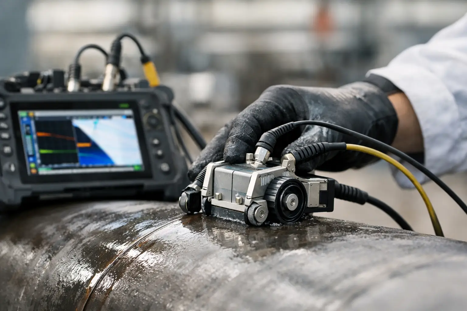

A scanner can look mechanically stable while the encoded data quietly falls apart. Missing positions, irregular scan increments, a frozen count or a B-scan that stretches and compresses are all reasons to ask: what causes encoder signal loss? In PAUT and ToFD work, an encoder fault is not just an inconvenience. It can compromise position accuracy, sizing confidence and the traceability of the inspection record.
The practical point is that encoder signal loss is rarely caused by the encoder alone. The fault may sit in the wheel-to-surface contact, scanner mechanics, cable path, connector, instrument configuration or the electrical environment around the scan. Finding it quickly means separating a genuine loss of pulses from a setup issue that only looks like one.
What Causes Encoder Signal Loss During PAUT Scanning?
Most PAUT scanners use an incremental quadrature encoder. As the wheel turns, the encoder sends two pulse trains, generally called A and B channels, to the instrument. The phase relationship between those channels lets the instrument determine movement and direction, while the number of pulses determines distance.
Signal loss occurs when the instrument does not receive, recognise or correctly count those pulses. It may be complete, where the position remains at zero, or intermittent, where the scan records uneven travel. Intermittent faults are often harder to diagnose because the encoder may count correctly during a bench check, then fail once the scanner is moving over a weld cap, coating edge or rough corrosion surface.
The main causes usually fall into mechanical drive problems, damaged signal paths, electrical interference and configuration errors. Several can exist at once, particularly on equipment that has spent time in the field.
Loss of Wheel Contact and Mechanical Slip
An encoder only measures wheel rotation. It assumes that wheel rotation equals scanner travel. If the wheel slips, lifts, skates across a surface or bridges a local feature, the encoder can still produce a clean electrical signal while the position data is wrong.
This is common on uneven weld profiles, heavily scaled material, wet surfaces, small-diameter pipe and surfaces with abrupt changes in coating condition. Too little wheel preload allows slip. Too much preload can make the scanner harder to push, increase wear and cause the wheel to climb or chatter over local features. The right setting depends on the scanner, wheel material, surface condition and travel direction.
Check that the encoder wheel is clean and turns freely, with no damaged tread or packed debris. Then watch the live encoder count while moving the scanner over the actual inspection surface, not just along a smooth bench. If the count stalls or jumps at the same location, the issue is likely mechanical contact or scanner stability rather than an electrical fault.
Backlash in drive components can also affect direction changes. Loose gears, worn couplings, a slipping hub or a poorly secured encoder mount can create delayed counts or inconsistent reversal behaviour. For encoded raster scans, this can show up as positional offsets between adjacent scan lines.
Surface condition changes the diagnosis
A scanner that performs properly on prepared carbon steel may lose positional accuracy on a rough weld crown or a surface carrying overspray, moisture or loose scale. Cleaning a narrow wheel track can be more effective than changing electronic settings. Where preparation is limited, use a scanner arrangement and wheel configuration suited to the surface rather than forcing a general-purpose setup onto a specialised job.
Damaged Cables, Connectors and Strain Relief
Encoder cables are exposed to repeated bending, dragging, crushing and connector loads. Internal conductor damage commonly produces an intermittent fault: the encoder works until the cable is bent near the connector, caught under a scanner frame or pulled tight at the end of a scan.
Start with the simple checks. Inspect the full cable length for flattened sections, cuts, exposed shielding and tight bends. Examine both connector faces for bent, recessed or contaminated pins. A connector can appear fully mated but make poor contact if the locking ring is loose, the insert has rotated or the pins are carrying dirt, moisture or corrosion.
Move the cable gently while monitoring the live encoder value. Do this with the instrument and scanner stationary, then repeat while turning the wheel slowly. If the count drops out when the cable is flexed at one point, stop using the cable until it is repaired or replaced. An intermittent cable should not be accepted because it happened to work for one scan.
Strain relief matters as much as cable condition. Route the lead so it has enough slack for the full scanner travel and cannot snag on clamps, weld reinforcement, a pipe support or the operator's boot. Avoid running it under the scanner or through a path where it repeatedly flexes at the connector. A neat cable route reduces both signal faults and accidental damage during a long shift.
Electrical Noise and Poor Shielding
PAUT inspections are often carried out close to welding equipment, generators, VSD-driven motors, magnetic yokes and power leads. Those environments can introduce electrical noise into low-level encoder signals, particularly where shielding is damaged or cable routing is poor.
Noise does not always look like a total loss of signal. It may create false counts, unstable position values or random directional changes. On the scan display, this can appear as local distortion that does not match the scanner's actual movement.
Keep encoder leads separated from high-current and switching power cables where practical. Crossing at right angles is preferable to running parallel over a long distance. Confirm that shielded cables are used where the system requires them, and do not defeat connector shielding with makeshift repairs. If the fault only appears when nearby equipment is operating, electrical interference becomes a strong suspect.
Grounding can be more complex. A poor ground may increase susceptibility to noise, but adding arbitrary ground connections can create ground loops. Follow the instrument and scanner requirements, use serviceable cables and test the system in a quieter electrical environment before changing the grounding arrangement.
Incorrect Instrument Setup or Encoder Scaling
Sometimes the encoder is producing pulses correctly, but the instrument is set to interpret them incorrectly. The result can be a scan that appears to lose position, travels too far on screen or records the wrong direction.
Confirm that the selected encoder input matches the physical connection, and that the instrument is configured for the correct encoder type and resolution. Pulse-per-revolution settings, wheel circumference and scan resolution need to agree with the scanner hardware. A mismatch will not necessarily stop counting, but it will make the distance display unreliable.
Direction settings deserve particular attention after cables have been changed or a scanner has been reconfigured. If the position count decreases during forward travel, the A and B channels may be reversed in the setup or wiring. Some instruments can compensate in software, but the correction should be documented and verified with a measured travel check.
Before scanning production work, move the scanner across a known distance and compare the displayed distance with a tape measure or rule. This takes little time and catches scaling errors that could otherwise be mistaken for encoder failure.
Connector Compatibility and Pin-Out Errors
Not every encoder connector that physically fits is electrically compatible. Different scanner brands and instrument families can use different pin-outs, supply voltages, signal formats or channel assignments. An adapter cable must preserve the required connections, shielding and channel order.
A wrongly wired adapter may cause no reading, reversed direction, partial counting or erratic behaviour. Do not assume a cable is correct because it was supplied with similar equipment or because the connector shell mates properly. Verify the pin-out against the encoder and instrument documentation, particularly when using a replacement cable, extension lead or custom adapter.
This is also relevant when mixing scanner components. Modular equipment is practical because it can be adapted to the job, but each change introduces a configuration check. Test the encoder and travel calibration whenever the scanner, instrument, lead or adapter arrangement changes.
A Field Method for Isolating the Fault
When encoder data becomes unreliable, avoid changing multiple things at once. Start by observing the live count while turning the encoder wheel by hand. If there is no count, check the instrument input, connector seating and cable condition before pulling apart the scanner.
If the count works by hand but fails during travel, inspect wheel contact, preload, scanner alignment and cable snagging. If the count is present but distance is incorrect, verify resolution, wheel dimensions and scaling. If the fault is random and appears near operating equipment, inspect shielding and cable routing for electrical interference.
A useful isolation test is substitution. Connect a known-good cable or encoder, one at a time, while keeping the remaining setup unchanged. This is faster and more reliable than guessing from symptoms, particularly where the fault is intermittent.
Protecting Data Quality Before the Scan Starts
Encoder checks should be part of the pre-scan routine, not a response after a questionable file has been collected. Confirm smooth wheel rotation, secure mounting, clean connectors, strain-free cable routing, correct direction and measured travel accuracy. Then check again after any hard knock, scanner rebuild or cable change.
Position data is part of the inspection result. Treat the encoder path with the same discipline applied to probe selection, wedge condition and calibration. A few minutes spent proving the scanner is counting real travel can prevent a repeat inspection when access, permits and shutdown time are far harder to recover.