
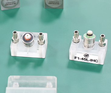

A wedge that starts leaving a dry track, develops a polished scan face or no longer sits cleanly on the component is not just a cosmetic issue. It changes the interface between the probe and the job. So, why do PAUT wedges wear? Mostly because they are the sacrificial contact surface in a system that combines pressure, sliding friction, couplant, heat and real-world steelwork.
For field inspection teams, wedge wear is normal. The important question is whether it is controlled, recognised early and accounted for before it affects calibration confidence or inspection coverage.
PAUT wedge wear starts at the scan surface
A PAUT wedge supports and positions the array, establishes the beam entry angle and provides the sound path needed to inspect the target zone. Its scan face is deliberately the part that contacts the component. Every metre of encoded scanning removes a small amount of material, even when the component appears smooth.
The wear rate depends on the job. A short weld scan on clean, machined pipe may barely mark a wedge. A corrosion mapping campaign over rough, coated or blast-cleaned steel can consume a scan face far more quickly. Weld caps, spatter, sharp transitions, scale and embedded grit all turn the component surface into an abrasive.
Wear is also rarely perfectly even. A wedge may round off at its leading edge, wear more heavily along one side, or develop grooves that follow the scan direction. Uneven wear matters because it can change how the wedge sits on the component and how consistently it couples during a scan.
Why do PAUT wedges wear faster on some jobs?
There is no single cause. In practice, wedge life comes down to the combined effect of surface condition, contact load, scanning method and wedge selection.
Rough steel and contamination act like abrasive media
The biggest contributor is usually the component itself. Mill scale, corrosion products, weld spatter, grinding marks and loose particulate all increase friction. A wedge sliding over clean steel sees relatively predictable contact. A wedge running across a rough weld toe, uneven parent material or neglected coating sees repeated high points digging into the scan face.
Loose grit is particularly damaging. It can become trapped between the wedge and the component, then score the wedge as the scanner moves. This is why a wedge can look acceptable after several hours on one job and show obvious tracks after a single shift elsewhere.
Removing loose scale, slag and debris from the scan path before starting will not make a poor surface smooth, but it prevents needless abrasion. It also improves coupling stability, which is usually the more immediate inspection benefit.
Excessive contact pressure increases friction and heat
A scanner needs enough contact pressure to maintain coupling and stay on track. More force is not automatically better. Once the wedge is already making reliable contact, extra downforce increases drag, raises local heat and accelerates material loss.
This often appears when a technician is trying to overcome a poor surface, an unstable scanner setup or cable drag. The scanner may be tightened down until it feels secure, but the wedge then becomes the point absorbing the load. On a long scan, that can produce rapid polishing, deformation at the leading edge and uneven wear across the face.
The practical target is stable coupling with the lowest pressure that keeps the scanner controlled. If consistent coupling requires excessive force, inspect the surface preparation, scanner alignment, wheel condition and cable management before simply adding more load.
Long scan distances make small losses add up
Wedges wear through accumulated travel. A manually manipulated probe may only travel a few metres during a weld examination. An encoded scanner used for corrosion mapping or repeated production work can travel hundreds of metres over a campaign.
This is where purpose-built hardware makes a difference. A scanner that tracks cleanly and holds the probe square reduces side loading and unnecessary scrub. A setup that wanders, binds on a weld profile or pulls against a stiff cable can wear one edge of the wedge much faster than the rest.
Travel speed can contribute as well. Fast scanning over rough material increases frictional heating and gives the wedge less opportunity to ride smoothly over local surface changes. The right speed is the one that maintains encoded data quality and stable coupling, not simply the fastest possible pass.
Couplant, temperature and site chemicals affect wedge material
Couplant is necessary, but it does not eliminate wear. It reduces friction when a consistent film is maintained, yet it can be displaced by rough surfaces, high contact pressure or rapid travel. A dry or intermittent coupling track often means the wedge is seeing more direct sliding contact than expected.
Temperature is another variable. Hot components can soften some wedge materials, while cold conditions can make them less forgiving of impact and local stress. The effect depends on the wedge material and the actual component temperature, not just the ambient weather.
Site chemicals deserve consideration too. Cleaning residues, process fluids and aggressive couplants may affect certain plastics over time. If the wedge face becomes tacky, crazed, swollen or unusually brittle, treat that as a material compatibility issue rather than ordinary abrasion.
The wedge may not match the surface or application
A wedge designed for a flat plate will not behave the same way on small-diameter pipe. A wedge intended for a smooth, prepared weld can wear quickly when used over heavily profiled surfaces. Curvature mismatch concentrates pressure into a smaller contact area, increasing drag and causing wear at the contact edges.
Probe and wedge compatibility matters just as much. The wedge must hold the probe correctly, with the intended aperture position and beam direction. A poor mechanical fit can allow micro-movement between probe and wedge, creating inconsistent contact and premature wear around the wedge body or retaining features.
Sometimes the answer is not a tougher wedge material. Harder materials may improve abrasion resistance but can trade away conformity, coupling behaviour or ease of machining. The suitable choice depends on the surface, temperature, geometry and inspection procedure.
Why small wedge changes can affect PAUT results
A worn wedge does not necessarily make an inspection invalid the moment a mark appears. Normal polishing and light, uniform wear are expected. The concern is when wear alters the wedge geometry enough to change the relationship between the probe, the component and the calibration.
As the scan face wears, the sound path through the wedge can change. The exit point, wedge delay and effective refracted angle may no longer match the values used during setup. On curved surfaces, uneven wear can also change the way the wedge seats from one side of the scan to the other.
That has practical consequences. Positional accuracy can drift, coverage near the weld toe can change, and amplitude response may become less repeatable. In encoded work, a worn or rocking wedge can combine with variable coupling to produce data that looks less trustworthy than the operator expects.
This is why calibration checks are not paperwork. They are the control that tells you whether the probe-wedge assembly still behaves as configured. If the wedge condition has changed noticeably, recheck the relevant reference responses and geometric settings in line with the approved procedure.
Control wedge wear before it becomes downtime
Wedge life improves when it is managed as part of scanner setup, not treated as an afterthought once data quality falls away. Before a job, inspect the scan face under good light. Look for deep grooves, a rounded leading edge, local steps, cracks, embedded debris and asymmetrical wear. Check that the wedge sits flat and does not rock on a representative section of the component.
During scanning, watch the couplant track and listen to the scanner. Increased drag, chatter or a sudden need for more downforce usually points to a surface, alignment or contamination problem. Stopping early to clean the path can save a wedge and prevent a long run of questionable data.
For repeat work, keep simple records of wedge use against material condition and scan distance. It does not need to be complicated. Knowing that a particular wedge lasts across a certain number of smooth-pipe scans but not over abrasive weld overlay helps with job planning and spares allocation.
A practical field routine should include these checks:
- Clean loose debris from the intended scan path before setting up.
- Set scanner pressure for stable coupling, not maximum preload.
- Route cables so they do not pull the scanner sideways.
- Confirm the wedge suits the component curvature and weld profile.
- Inspect the scan face at breaks and after any impact or snag.
- Repeat required calibration checks when wedge condition changes.
Where a replaceable wear surface or a purpose-designed scanner arrangement is available, it may reduce the cost and disruption of routine wear. The trade-off is that any additional interface or accessory must be suitable for the inspection configuration and verified through calibration. Do not add protective layers simply because they look helpful if they change the sound path or compromise procedure compliance.
When should a PAUT wedge be replaced?
Replace or refurbish a wedge when its condition prevents stable seating, produces inconsistent coupling, changes the calibrated response beyond acceptable limits, or shows damage that could worsen in service. Deep scoring, cracking, distortion and obvious one-sided wear are clear warning signs. A wedge that needs excessive pressure to couple is also telling you something useful.
There is no universal scan-distance limit because a wedge used on clean plate and one used on rough, scaled pipe have completely different lives. Condition-based decisions, backed by documented calibration checks, are more reliable than replacing wedges on a fixed calendar interval.
A PAUT wedge is a consumable interface, not a permanent reference artefact. Treat it accordingly: choose it for the job, keep the scan path as clean as practical, monitor its geometry and change it before a small wear problem becomes an inspection confidence problem.