
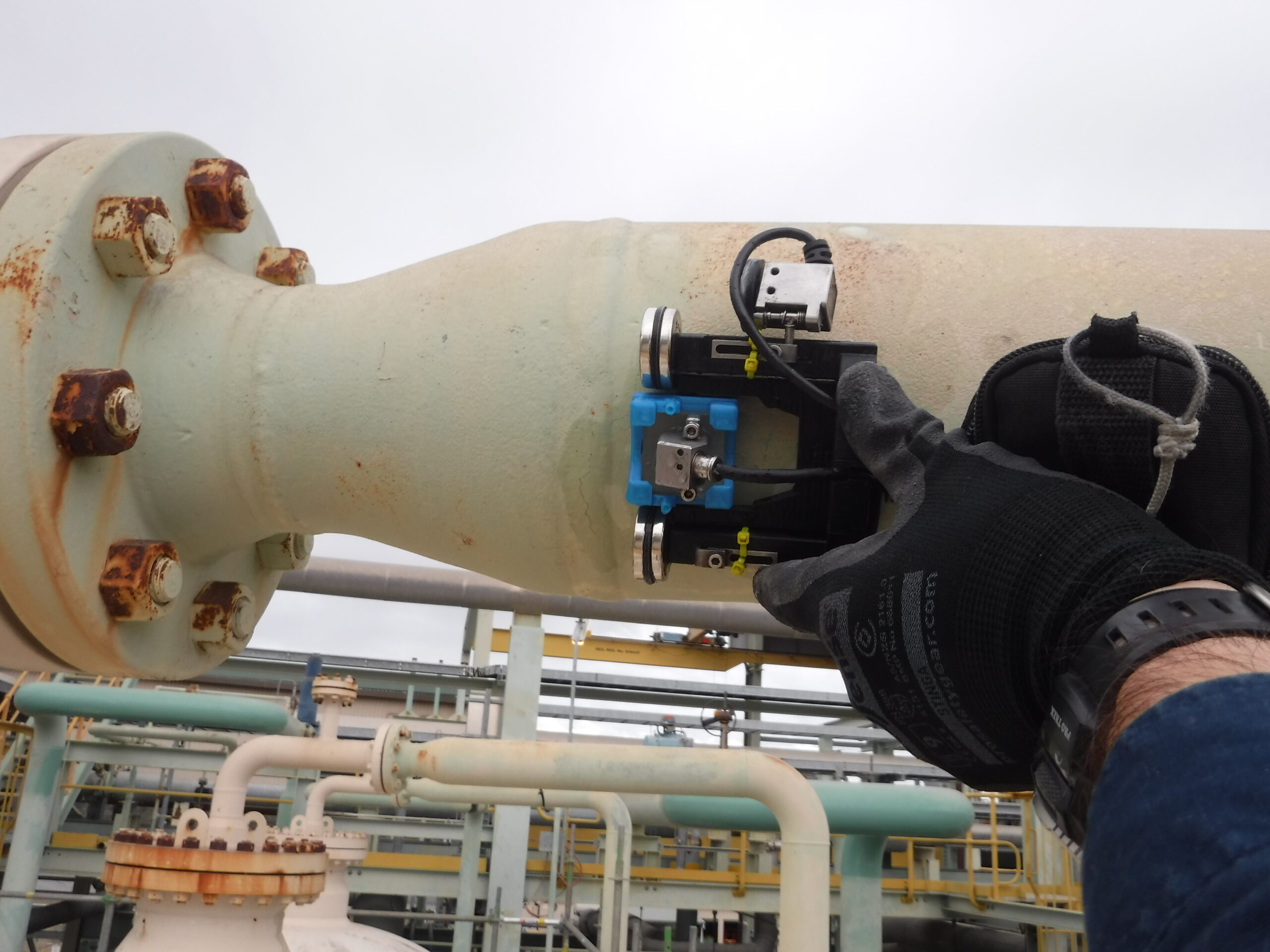

An encoded PAUT scan can look clean, repeatable and fully covered while still reporting the wrong position. A loose drive wheel, incorrect pulses-per-millimetre setting or reversed direction can shift indications, distort lengths and make a scan difficult to reproduce. Knowing how to calibrate PAUT encoders is therefore not just an instrument setup task. It is part of making the scan defensible.
For field inspection, encoder calibration needs to account for the complete system: the scanner, wheels or chain, encoder, cable, acquisition unit and the surface being scanned. The instrument can only display the position information it receives. If the mechanical setup slips, lifts or runs over inconsistent geometry, a correct software value alone will not fix the result.
What PAUT encoder calibration actually checks
In most PAUT applications, encoder calibration verifies that a measured physical travel produces the correct travel shown in the acquisition software. The primary scan encoder controls the scan-axis position - often referred to as the X-axis - while a second encoder may record probe index or lateral movement on the Y-axis.
The result is usually expressed as pulses per millimetre, counts per millimetre, or a similar unit depending on the instrument. The software uses this value to turn encoder pulses into a position along the component. If the value is wrong by 2%, a 500 mm scan can be out by 10 mm. That may be enough to affect reported indication position, length sizing, coverage confidence and the ability to return to a specific location.
Calibration also confirms direction. If travel forward is displayed as negative movement, the scan may be mirrored or recorded in the wrong orientation. This is easily corrected in software, but it should be corrected before production data is collected, not after the report is being prepared.
Start with the mechanics, not the menu
A common mistake is to begin by entering a known encoder resolution into the flaw detector or PAUT instrument. That is a useful starting point, but it is not calibration of the working scanner assembly.
First inspect the hardware as it will be used on the job. Check that the encoder is securely mounted, the wheel or drive mechanism turns freely, and there is no visible damage to the cable or connector. Confirm the wheel has consistent contact with the surface and is not riding on weld cap, heavy scale, spatter or a changing edge condition.
For a wheeled scanner, look for wear on the tyre or O-ring. A worn wheel has a smaller effective circumference, which changes the travel per revolution. On a chain scanner, check chain tension, link engagement and whether the chain tracks consistently around the pipe. On magnetic or track-based systems, make sure the scanner sits flat and does not rock as it moves.
Backlash matters too. Gently move the scanner forward and backward while watching the encoder position. A small amount of movement before the count changes indicates play somewhere in the drive train. That does not always make the scanner unusable, but it means scan direction should be controlled and reversal during acquisition should be avoided where possible.
How to calibrate PAUT encoders with a known distance
The most reliable field method is to run the scanner over a known physical distance and allow the instrument to calculate, or confirm, the encoder value. Use a flat, stable surface where possible. A steel rule, marked calibration plate or accurately measured line on the component can work, provided the marks are clear and the scanner can travel naturally between them.
Set the scanner at the first reference mark and zero the encoder position in the acquisition software. Move it to the second mark in the same direction and at a steady pace. The distance should be long enough to make small errors visible. A 100 mm check may be acceptable for a compact scanner, but 300 mm, 500 mm or more gives a better indication of cumulative error when the job allows it.
Compare the displayed travel with the actual known distance. If the software has an encoder calibration function, enter the known distance and let it calculate the revised pulses-per-millimetre figure. If it requires manual entry, adjust the value according to the instrument procedure, then repeat the run.
Do not accept the first pass automatically. Run the scanner back to the start, re-zero, and repeat the check at least once. If the result changes materially between runs, stop adjusting software values and find the mechanical cause. Typical causes include wheel slip, inconsistent wheel loading, a loose encoder coupling, cable faults or a marked distance that was not measured accurately.
Check accuracy across the practical scan range
A scanner can agree over a short distance and still drift over a long scan. Where the inspection procedure involves 1,000 mm of weld length, long corrosion mapping strips or multiple circumferential passes, verify performance over a representative distance.
As a practical acceptance check, the allowable error should be driven by the inspection procedure, customer requirement and reporting tolerance. For general positioning work, a repeatable result within a few millimetres over the relevant scan length may be acceptable. For encoded sizing, automated analysis or critical location reporting, tighter control may be required.
The key point is repeatability. If the scanner reports 500 mm on one pass and 494 mm on the next, the issue is not simply a calibration number. The system is not tracking travel consistently.
Confirm encoder direction and axis assignment
Before scanning a weld or corrosion area, move the scanner in the intended inspection direction and watch the position display. Confirm that increasing encoder position matches the direction stated in the scan plan and report convention.
For weld inspection, that may mean left to right when viewed from a nominated datum, or increasing distance from a weld start reference. For pipe work, establish whether the encoded direction represents axial travel, circumferential travel or probe index. Record the convention so the technician reviewing the data does not need to guess what positive movement means.
Where two encoders are fitted, verify both separately. The scan axis and index axis are easy to confuse after changing cables or scanner configurations. A scan can be acquired with plausible-looking data while the axes are swapped, particularly when the probe carriage is moved manually.
If the software offers encoder direction inversion, use it rather than rewiring or mechanically reversing the scanner unless the setup requires it. Then repeat the known-distance check after the change.
Calibrate in the same condition as the inspection
Encoder calibration is condition-dependent. A scanner calibrated on a smooth bench plate may not track identically on a painted pipe, a corroded tank shell or a surface with heavy profile. This does not mean every setup needs excessive calibration work. It means the check needs to reflect the risk in the job.
For smooth, straight plate scanning with a well-maintained wheeled scanner, a pre-job verification may be enough. For small-diameter pipe, irregular surfaces, vertical scanning or long corrosion mapping runs, calibrate on a representative section where possible and watch for slippage during the first production pass.
Temperature can also affect practical performance. Soft wheel materials, dirty surfaces and moisture can alter traction. In remote or shutdown work, it is worth rechecking the encoder after the scanner has been moved, knocked, reconfigured or used on a significantly different surface.
Common faults and what they usually mean
If encoder position does not change, start with the simple causes: wrong encoder channel selected, loose connector, damaged cable or an encoder not engaged with its wheel or drive. If counts jump intermittently, inspect the cable for strain and check the connector pins for contamination or damage.
If the displayed distance is consistently too long or too short, the pulses-per-millimetre setting is likely incorrect, or the wheel diameter has changed through wear or replacement. Recalibrate over a known distance rather than relying on a nominal wheel specification.
If the error varies from one pass to the next, look for slip, lost traction, chain movement, backlash or scanner rocking. A software correction may make one run appear correct while leaving the underlying fault in place.
If the position reverses or becomes erratic during a scan, consider how the operator is handling the scanner. Encoded acquisition is usually most reliable when movement is steady and in one direction. Stop-start scanning and frequent reversal can introduce positional uncertainty, especially in systems with mechanical play.
Record the check so the scan can be defended
A short record is enough, but it should exist. Note the scanner identification, encoder channel, calibration distance, displayed distance, direction convention and date. If the project has a formal inspection procedure, follow its calibration and verification requirements rather than relying on a generic tolerance.
For owner-operators and small inspection teams, this discipline pays off when a client asks how an indication location was established or when a scan needs to be repeated months later. It also makes it easier to identify a wheel, encoder or cable that is beginning to cause trouble.
PAUT.Tech scanner systems are built around task-specific setups, but the same rule applies to every encoded scan: validate the encoder on the configuration and surface you are actually using. A two-minute travel check before acquisition is far cheaper than explaining a positional error after the job is complete.