
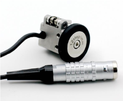

A scan can look stable on the screen while its position data is quietly drifting. That is the problem with encoder slippage: a few missed or false millimetres may not be obvious during acquisition, but they can distort sizing, misplace an indication or make repeat coverage difficult. Knowing how to prevent encoder slippage starts with treating the encoder as part of the inspection system, not just an accessory on the scanner.
For PAUT and ToFD work, encoder accuracy depends on consistent mechanical contact, a rigid scanner setup and calibration that reflects the surface being inspected. A clean, controlled workshop plate is one thing. A painted pipe, a rough weld cap or a corroded vessel wall in the field is another.
Why encoder slippage matters in encoded scanning
An encoder converts scanner travel into position information for the instrument. If the wheel turns less than the scanner moves, the acquired data is compressed against the true distance. If it turns without real travel, the data is stretched. Either condition can affect encoded B-scans, C-scans and merged coverage maps.
The practical consequence is not always a failed scan. More often, it is reduced confidence. An indication may appear at the wrong distance from a datum, scan overlap may be less than planned, or a manual re-scan may not line up with the first pass. On a weld examination, that can complicate reporting and verification. On corrosion mapping, it can create an inaccurate picture of remaining wall distribution.
Slippage is also often blamed for issues caused elsewhere. A loose connector, damaged cable, incorrect encoder resolution or intermittent instrument input can produce missing counts that resemble wheel slip. The first job is to separate a mechanical tracking problem from an electrical or configuration problem.
How to prevent encoder slippage before scanning
The best time to find a tracking issue is before the probe touches the inspection area. Set the scanner on the actual component, or on a representative sample with comparable surface condition and curvature. Then move it over a known measured distance and compare encoder travel with a tape measure or marked reference.
Run this test in both directions. A scanner that reads correctly in one direction but not the other may have backlash in the drive arrangement, a wheel that is lifting during reversal, or a mounting point that is shifting under hand pressure. Repeat the movement at the speed expected during the scan. A slow bench check can miss a problem that appears when the scanner is pushed at production pace.
Before acquisition, check four things:
- The encoder wheel is clean, dry and free of couplant, grinding dust, scale or loose paint.
- The wheel has enough contact pressure to track, without loading the scanner so heavily that movement becomes uneven.
- The encoder bracket, axle and scanner frame have no visible movement or loose fasteners.
- The cable, connector and instrument channel produce stable counts when the wheel is rotated by hand.
These checks take little time and are generally faster than investigating questionable positional data after the job.
Start with wheel contact and surface condition
The encoder wheel needs a surface it can grip consistently. Smooth, dry steel usually presents few problems. Painted surfaces, wet coatings, loose rust, blast profile, weld spatter and oily contamination are more difficult because they reduce friction or make the wheel ride over an uneven layer.
Clean only the track required for the encoder where the procedure and site conditions allow it. Removing loose scale and excess couplant from the wheel path is usually more effective than increasing preload. More force can help on a smooth surface, but on a rough surface it may cause the wheel to bounce, wear faster or push a lightweight scanner off its intended path.
Wheel material and tread profile matter as well. A hard, smooth wheel can work well on clean machined material yet struggle on a coated pipe. A grippier wheel may improve tracking on difficult surfaces, but can collect debris or wear more quickly. There is no single best wheel for every job. Match it to the surface, scan direction and expected exposure to dirt, moisture and couplant.
Curvature needs particular attention. On small-diameter pipe, the encoder wheel may contact at an angle or sit on a high point while the scanner body follows a different path. That changes the wheel's effective rolling diameter and can introduce position error even without obvious slipping. Use a scanner configuration designed for the component diameter where possible, rather than forcing a flat or oversized arrangement to do a pipe job.
Set preload without creating drag
Encoder preload is a balance. Too little and the wheel skates, especially at a change in surface texture or when crossing a weld. Too much and the scanner becomes harder to drive, which can create jerky motion and inconsistent probe contact. Excess force can also accelerate wheel and axle wear.
Set the wheel so it stays in contact through the full travel, including transitions across weld reinforcement, surface steps and changes in pipe orientation. With the scanner in place, apply the same light side load and forward pressure that will be used during scanning. If the encoder bracket flexes or the wheel visibly unloads, adjust the mounting arrangement before proceeding.
The scanner itself must be stable. A poorly supported frame, loose guide wheel or flexible probe holder can shift the load away from the encoder wheel as the operator moves. This is why purpose-built, task-specific scanner setups are generally more repeatable than a single scanner rebuilt for every application. PAUT.Tech designs modular hardware around that field reality: the more naturally the scanner fits the job, the fewer compromises are required to make it track.
Calibrate encoder distance on the job surface
Correct pulses-per-millimetre settings are essential, but they are not a permanent truth for every setup. The nominal circumference of an encoder wheel may not reflect its loaded rolling diameter on a curved, coated or rough component. Wheel wear can also change the result over time.
Calibrate the encoder over a meaningful distance, not just a short movement. A 500 mm or 1,000 mm reference is more useful than a 50 mm check because small errors are easier to see. Record the measured travel, compare it with the instrument display, and adjust only when the error is repeatable.
Do not calibrate on a clean strip of steel and assume that value applies to a heavily coated scan path nearby. If the inspection surface changes substantially, verify again. This is particularly relevant when moving from parent material to a weld zone, changing from longitudinal to circumferential scanning, or relocating to a different pipe diameter.
Also confirm that the instrument encoder configuration matches the hardware. Check quadrature settings, direction, resolution, units and any encoder divider settings. A configuration error can produce a consistent distance discrepancy, while genuine slippage is more likely to vary with surface condition, direction or operator pressure.
Use scan technique that protects positional accuracy
Even a well-set encoder can be defeated by inconsistent handling. Start each encoded pass from a clear datum and allow the scanner to settle before recording. Keep travel speed steady. Sudden starts, stops and direction changes increase the chance of wheel skid, particularly on damp or contaminated material.
Avoid pulling the scanner sideways against its guides. Side loading can reduce encoder contact or force the wheel to scrub rather than roll. If the scanner must negotiate a complex geometry, assess whether a different guide arrangement, magnetic support, track or dedicated scanner frame is needed.
For longer scans, include practical verification points. Mark known distances on the component where permitted, or use recognisable geometry such as plate edges, weld centres or reference marks. If the encoded position does not agree at these points, stop and investigate rather than carrying the error through the rest of the scan.
A useful field routine is to make one controlled verification pass before production acquisition. Check distance accuracy, observe the live encoder count for dropouts, then reverse over part of the same path. If forward and reverse travel disagree, do not compensate by guessing. Inspect the wheel, preload, mount and cable first.
Know when the encoder wheel is the problem
Encoder wheels are wear items. Flat spots, embedded metal particles, hardened couplant residue and worn tread all reduce reliable contact. A wheel may still turn freely by hand yet lose grip under scanner load.
Inspect the wheel regularly and replace it before wear becomes a reporting risk. Check the axle for play and make sure the wheel rotates without binding. If repeated calibration produces different values on the same surface, suspect mechanical wear or a shifting mount. If counts disappear while the wheel is turning steadily, inspect the cable and connector as closely as the wheel itself.
The aim is not to make every scanner configuration more complicated. It is to make tracking predictable. A clean wheel, appropriate preload, rigid mounting and a short distance verification on the real component will prevent most encoder slippage before it has a chance to affect the scan. When positional data matters, give the encoder the same setup discipline as the probe and wedge.