
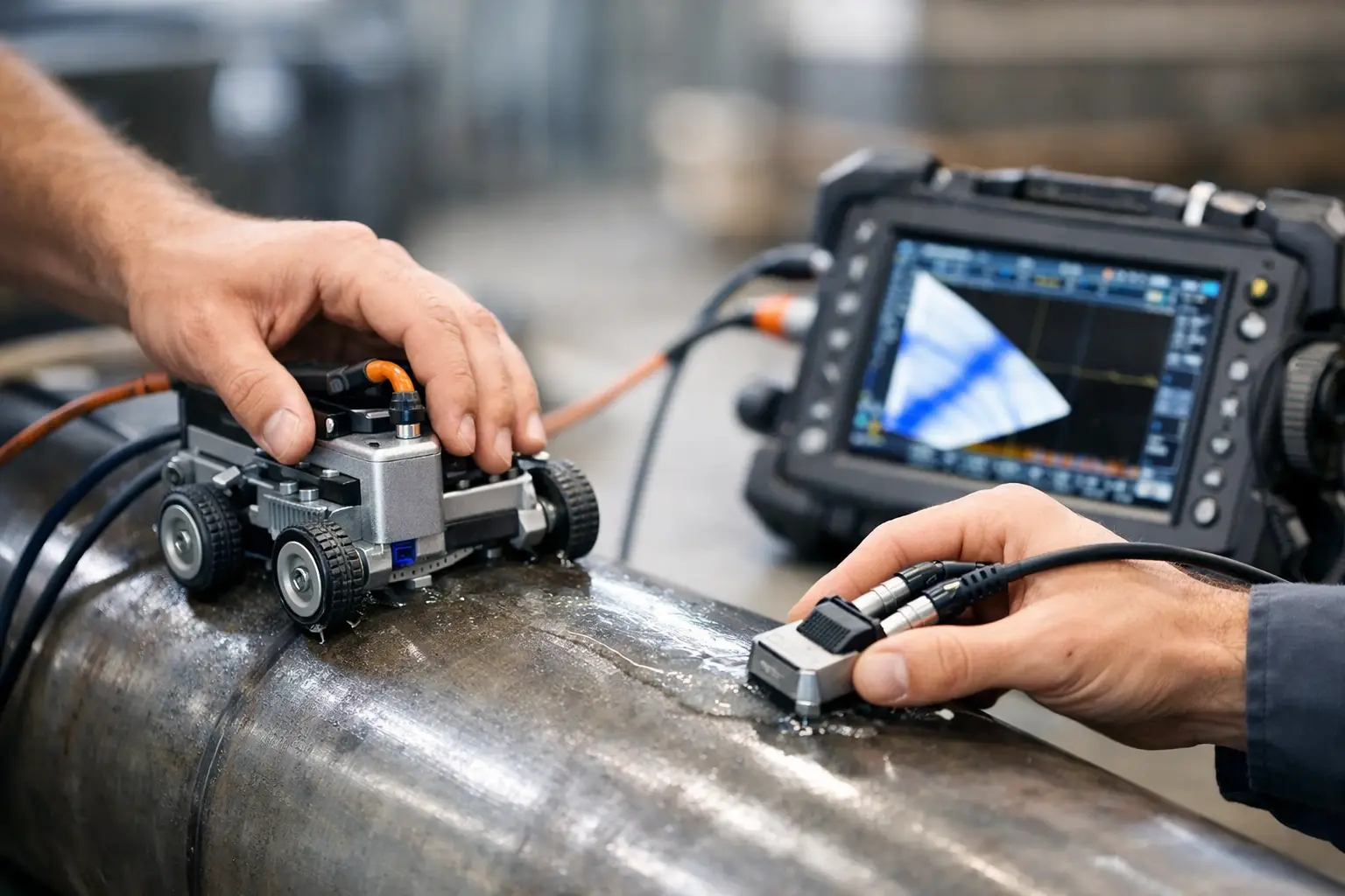

A scan can look clean on the screen while still carrying poor positional data. When an encoder skips, slips or reports movement that does not match the scanner’s actual travel, indications may be placed in the wrong location, sizing can become unreliable, and repeatability between passes disappears. Knowing how to improve encoder tracking starts with treating the encoder, wheel and scanner as one mechanical system rather than a software setting.
For PAUT and ToFD work, encoder quality matters most when you need defensible position data: weld mapping, corrosion profiling, length sizing, encoded raster scans and repeat inspections. A minor error over a short weld may be manageable. The same error over a long seam, or during a high-resolution corrosion scan, can turn into a meaningful location discrepancy.
What poor encoder tracking looks like
The obvious symptoms are a frozen position display, jumpy scan distance or an acquisition that stops and starts despite steady scanner movement. Less obvious faults are often more troublesome. A scan may be acquired without alarms, yet show stretched or compressed features, inconsistent indication positions between scan directions, or a reported scan length that does not match the component.
Before changing instrument settings, separate two questions. Is the instrument receiving every encoder pulse correctly? And is the encoder wheel producing an honest measure of physical movement? The first is electrical and configuration-related. The second is usually mechanical, surface-related or caused by scanning technique.
A quick field check is useful. Mark two points on the component at a known distance, run the scanner between them under normal scanning pressure, and compare displayed travel with the actual distance. Repeat the check in both directions. If the result differs by direction, look closely at wheel slip, backlash, encoder mounting and cable strain before recalibrating anything.
How to improve encoder tracking at the scanner
Start with firm, consistent wheel contact
An encoder wheel must remain in contact with the surface with enough normal force to rotate positively, but not so much force that the scanner binds or the wheel deforms. On smooth pipe, painted surfaces and lightly oxidised plate, a wheel can appear to be rolling while intermittently slipping under the load of a cable bundle or stiff probe lead.
Inspect the tyre or contact surface for wear, embedded grit, flat spots and contamination from couplant. Couplant on the encoder wheel is a common source of gradual positional error, particularly during long scans. Clean it before setup and again if scan performance changes during the job.
Surface condition changes the answer. A soft wheel may grip well on a smooth surface but struggle across heavy scale, weld spatter or sharp profile transitions. A harder wheel may survive abrasive work but transmit more vibration and lose contact over local irregularities. Match the wheel and scanner arrangement to the surface rather than expecting one configuration to suit every job.
Keep the encoder aligned with travel
The encoder should roll in the direction it is measuring. If it is cocked sideways, forced around a curve incorrectly or mounted where the scanner yaws during travel, the wheel can scrub rather than roll. That creates under-travel and makes the error dependent on operator direction and pressure.
Check that the scanner frame is sitting square to the intended scan path and that the encoder bracket has no free play. On pipe scanners, confirm the frame is properly tensioned and centred before setting the index point. On manual weld scanners, check that guide wheels or magnetic guidance are doing their job. An encoder cannot compensate for a scanner that wanders.
Also watch the effect of probe and cable drag. A probe cable pulled from one side can steer a light scanner, unload an encoder wheel or introduce periodic slip as the cable catches. Route leads so they are supported, have enough slack for the scan length, and do not pull against the scanner. This is especially relevant when scanning at height or around a vessel where the cable is hanging from the work area.
Calibrate the right encoder at the right resolution
Encoder calibration should reflect the wheel diameter, pulse count and the actual measurement path. If a wheel has been replaced, worn substantially or changed for another surface, verify the calibration. Do not assume a nominal wheel diameter remains accurate after field use.
Use a measured reference length that is relevant to the job. A very short calibration distance can hide small errors that become obvious over a metre or more. For longer encoded scans, validate over a longer distance where practical. The goal is not merely to make the calibration routine pass; it is to confirm that reported travel remains credible over the scan length you will acquire.
Resolution is a trade-off. Higher encoder resolution can provide finer spatial sampling, but it also makes the setup more sensitive to noise, missed pulses and inconsistent wheel motion. Set the encoder and acquisition parameters for the inspection requirement, probe aperture, scan speed and expected indication size. Collecting far more data than the inspection needs can increase file size and operator burden without improving the result.
Confirm direction, channels and acquisition settings
A reversed encoder direction is easy to spot. Incorrect channel selection or a loose encoder connection can be less obvious. Confirm the instrument is assigned to the correct encoder input, the intended axis is active, and the displayed direction matches physical travel before acquiring production data.
Check the encoder cable along its full length. Look for crushed sections, damaged strain relief, bent pins, loose locking rings and cable sections that flex sharply when the scanner moves. Intermittent faults often appear only when the cable is in a particular position. Wiggle testing at the bench can help, but a controlled movement test with the scanner assembled is more representative.
Where the instrument allows it, monitor encoder counts or position while moving slowly and steadily over a known distance. The count should rise consistently, with no sudden jumps or dead zones. If tracking fails only at normal scan speed, the issue may be acquisition speed, trigger settings or communication stability rather than the encoder itself.
Control the scan method, not just the hardware
Good encoder tracking is often lost through rushed handling. Starting with a sharp push, changing speed mid-pass, dragging the scanner sideways, or lifting a wheel to clear an obstruction can all corrupt position data. If the wheel loses contact, stop the acquisition and restart from a known reference where procedure and software allow. Continuing through a known tracking failure only creates data that must be questioned later.
For raster corrosion mapping, make sure index movement is deliberate and repeatable. The travel encoder may be working perfectly while the index pitch is inconsistent because the operator is estimating each step. Use scanner guides, indexed mechanisms or clear reference marks where the inspection method requires controlled coverage.
For weld scans, establish physical datum marks before scanning and verify the encoded zero against them. A reliable zero point gives the operator and reviewer a practical way to check that displayed position still agrees with the component. It also makes rescans and follow-up inspection far easier.
Build encoder checks into the pre-scan routine
A short setup routine prevents most avoidable tracking problems. Before production scanning, inspect the wheel and bracket, confirm cable condition and instrument assignment, verify direction, and run the scanner over a known reference distance. Then perform a short encoded test scan using the same probe load, cable routing and travel speed expected for the job.
Record any correction or calibration change under the job’s normal quality process. That matters when scan data may be reviewed later, compared with previous inspections or used to direct repair work. Position accuracy is part of the inspection result, not an accessory to it.
Purpose-built scanner hardware helps because it reduces the number of compromises in the setup. A scanner configured for the component, probe arrangement and travel path is less likely to twist, drag or unload its encoder than a general arrangement repeatedly rebuilt for different work. That practical fit is often worth more than adding complexity to the software settings.
The best encoder check is the one performed before the first production pass. If the scanner reports the same distance you can measure on the component, rolls consistently in both directions and stays stable at working speed, the encoded data has a sound mechanical foundation for the inspection decisions that follow.