
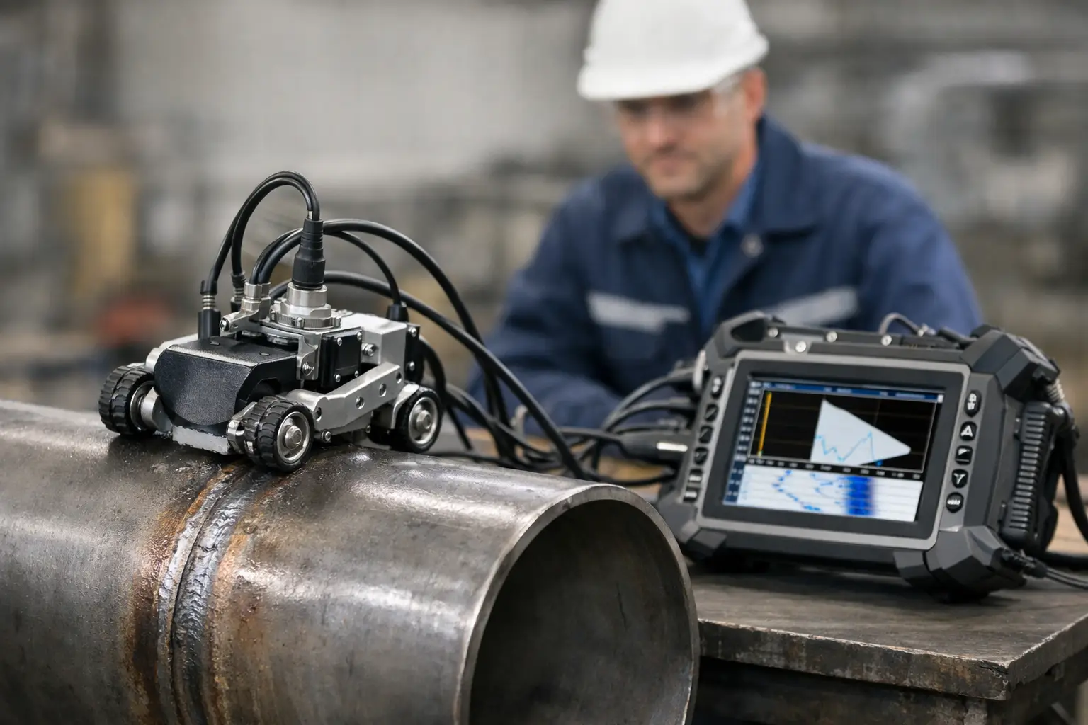

A weld scan can look tidy on the screen and still be hard to defend if the setup was rushed. This weld inspection setup example shows how a practical PAUT and ToFD arrangement can be planned for a typical butt weld, with enough detail to make the scan repeatable in the field rather than merely possible on the bench.
The objective is not to prescribe one configuration for every job. Material, wall thickness, weld preparation, access, applicable code, and the expected flaw mechanisms all change the answer. The aim is to establish a disciplined starting point: define the inspection volume, select hardware that can physically maintain the scan plan, calibrate against the actual setup, then verify coverage before production acquisition begins.
Weld Inspection Setup Example: 25 mm Carbon Steel Butt Weld
Consider a single-V butt weld in 25 mm carbon steel pipe or plate, inspected from the cap side after welding. The weld has a reasonably smooth cap, access is available on both sides of the centreline, and the procedure requires volumetric examination for planar welding imperfections. A PAUT scan provides the main inspection record, while ToFD can be added where accurate through-wall sizing and root-to-cap coverage are required.
For this example, use a 5 MHz linear-array probe with a suitable refracted longitudinal-wave wedge, or a shear-wave wedge where the approved procedure calls for it. The frequency is not selected because 5 MHz is universally correct. It is a workable starting point for 25 mm carbon steel where resolution is needed without excessive attenuation. On coarse-grained material, heavily clad components, or surfaces with poor coupling, a lower frequency may give a more usable signal-to-noise result.
The PAUT focal law plan should cover the weld volume and heat-affected zones from both sides. A sectorial scan might sweep from 40 to 70 degrees, with focal depths set to maintain useful response through the expected inspection zone. The exact angles depend on bevel geometry, cap condition, probe position and the need to avoid a blind area near the root or upper fusion faces.
Set the scan axis along the weld and use an encoded scanner to maintain position. A manual probe can find indications, but it is not the same as producing a reliable encoded record over several metres of weld. For a circumferential pipe weld, the scanner needs to hold the probe position and travel consistently around the pipe while keeping the encoder engaged. For a longitudinal seam, the same principle applies along the weld length.
Hardware arrangement
The scanner should be selected around the job, not forced to suit hardware already in the kit. On a straight plate weld, a compact linear scanner with a stable probe holder may be sufficient. On pipe, a chain, band or dedicated pipe scanner is usually the more practical choice because it follows the circumference and reduces the tendency for the operator to steer off line.
Place the PAUT probe at the calculated offset from the weld centreline. Mark the datum line, scan limits and probe index reference before coupling begins. If scanning from both sides, clearly identify side A and side B in the instrument file and inspection report. Small errors in orientation become major problems when an indication must later be located for repair.
A typical arrangement includes the encoded scanner, PAUT probe and wedge, probe holder, couplant feed or manual application method, and a reference block that matches the component material and thickness as closely as practical. Add ToFD probes only when the procedure and access support them. ToFD needs consistent probe separation and stable travel, so a scanner that flexes or slips will undermine the value of the technique.
PAUT.Tech hardware is designed around this reality: purpose-built, task-specific scanners reduce the time lost rebuilding one expensive frame between pipe, weld and corrosion jobs.
Start With the Inspection Volume, Not the Probe
A common setup mistake is choosing a probe first and trying to make the coverage work afterwards. Begin with the weld drawing or joint profile. Identify the root, fusion faces, cap, sidewall regions, expected heat-affected zone coverage, and any areas that cannot be interrogated effectively from the available surface.
For the 25 mm example, calculate whether the selected beam angles can strike the root and both fusion faces from the proposed offsets. Check the sound paths for excessive skip distance, mode conversion, beam spread and geometrical echoes. If a 45-degree beam reaches the root cleanly but misses the upper fusion face, changing the probe offset or adding a higher-angle focal law may solve the issue. If it does not, the scan plan needs another access position rather than optimistic interpretation.
This is also where practical access matters. A weld located beside a flange, nozzle, stiffener or clamp may prevent the required probe offset. A narrower wedge, smaller aperture, alternative scan direction, or a different scanner arrangement may be needed. There is no benefit in a technically elegant focal law that cannot be deployed consistently on the component.
Calibrate the Complete Assembly
Calibration applies to the complete inspection system: instrument, cable, probe, wedge, scanner, encoder and focal laws. Do not calibrate the probe on the bench and assume the field configuration remains unchanged after it is mounted in a holder and loaded against a curved surface.
Set wedge delay and sensitivity using the approved reference reflector and verify the sound path range covers the complete inspection volume. Establish the reference level in accordance with the governing procedure, then confirm amplitude response across the relevant angles and depths. A response that is satisfactory at one angle may fall away at another, particularly where the wedge, couplant or material condition affects transmission.
For encoded PAUT, verify encoder calibration before the production scan. Travel a known distance and compare the recorded length with the physical measurement. On pipe, check that the scanner does not slip as it moves around the circumference. Encoder errors distort indication length, position and image geometry, which creates avoidable doubt during reporting or client review.
If ToFD is included, set probe centre separation from the required depth coverage and verify lateral-wave and back-wall response. Confirm the dead zones are understood. ToFD is valuable for sizing, but it is not a substitute for coverage planning. Near-surface regions, cap condition and poor coupling can still limit what the data can show.
Run a Short Verification Scan First
Before committing to the production run, acquire a short scan over a representative section. Review the B-scan, S-scan and C-scan with the operator who will perform the work. This quick check often exposes issues that are invisible during setup: weak coupling at one side of the cap, an encoder dropout, excessive mechanical vibration, an unexpected geometry echo, or a focal law that does not provide adequate root response.
Check that the weld centreline sits where it should in the recorded image. Confirm the scan width captures the planned heat-affected zone and that the encoded length matches the physical travel. If the image is noisy, do not immediately increase gain. First inspect the surface condition, couplant, wedge wear, cable condition, probe pressure and scanner stability. More gain can make a poor setup look busier without making it more inspectable.
For production scanning, maintain a controlled overlap between adjacent passes where the scan width requires multiple tracks. Record scan direction, probe side, focal law file, calibration details, component identification and any access restrictions. If a section cannot be covered to procedure, document the limitation at the time. It is far easier to resolve while the job is still set up than after the equipment has been packed into the ute.
When This Example Needs to Change
This arrangement is a starting point for a conventional carbon steel butt weld, not a universal recipe. Thick sections may need different focal depths, multiple probe positions or lower-frequency probes. Thin wall pipe may need reduced angles and tighter control of the near-surface region. Austenitic welds, dissimilar metal welds, cladding and coarse-grained materials can require a completely different approach because beam steering, attenuation and anisotropy affect both coverage and interpretation.
Surface condition changes the setup as well. A rough cap, spatter, high-low or poor access can make a scanner-based plan less stable. In some cases, light surface preparation is the most efficient fix. In others, a smaller, more adaptable scanner or a revised inspection direction is the better answer. The correct choice depends on what produces reliable data without adding unnecessary site time.
A good weld inspection setup is not defined by the most complex scanner or the largest focal-law file. It is the arrangement that gives known coverage, repeatable encoded position and data an experienced technician can explain. Build the setup around the weld in front of you, verify it before production, and the final scan will carry far more weight when it matters.