
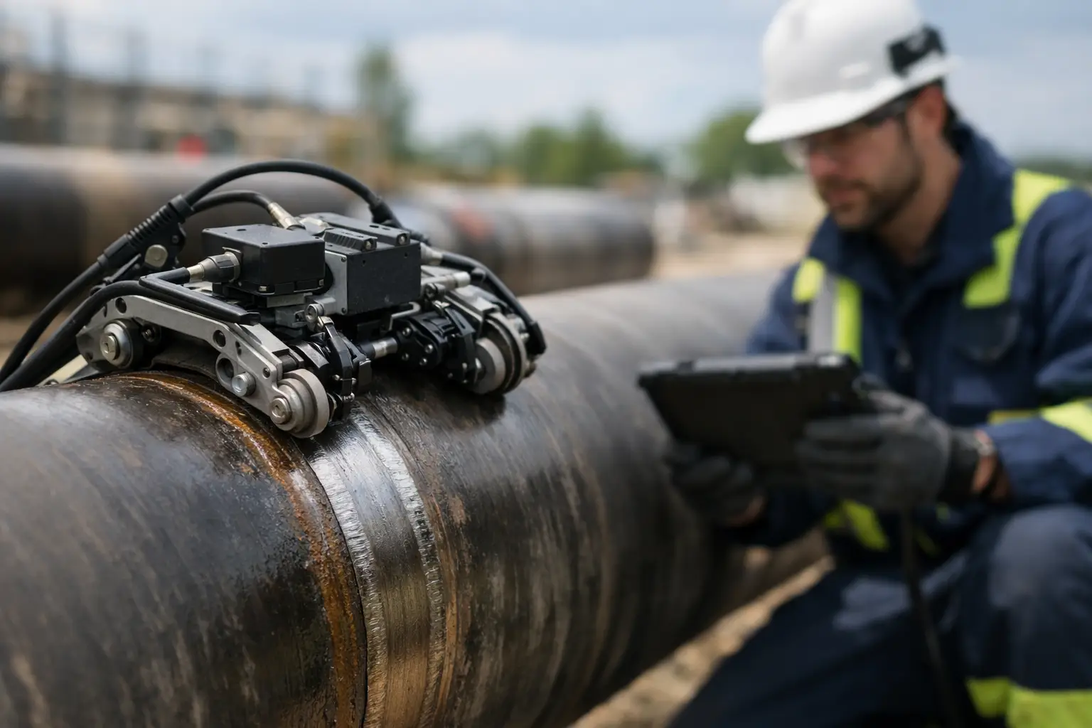

A girth weld scanner that looks capable on the bench can become the weak point of an inspection once it reaches a coated pipe, a tight work area, or a production schedule that will not wait for a rebuild. The best scanners for girth welds are not necessarily the largest or most expensive systems. They are the units that hold probe position, deliver reliable encoded data and suit the actual pipe, weld profile and inspection procedure in front of the technician.
For PAUT and ToFD work, scanner choice affects more than scan speed. It affects coverage confidence, repeatability, setup time and whether a technician can complete the job without fighting the hardware. A fit-for-purpose scanner also protects the inspection business from a common operational problem: having one costly scanner tied up on a routine weld while another job waits.
What Makes a Girth Weld Scanner Fit for Purpose?
A girth weld scanner must maintain controlled movement around the pipe circumference while carrying the required probes at a consistent index position. That sounds straightforward, but pipe diameter, weld cap condition, access, insulation clearance and surface condition can all change the requirements.
For most encoded PAUT and ToFD inspections, the scanner needs a stable encoder path and enough rigidity to prevent probe lift or side-to-side movement. The probe holders must allow meaningful adjustment of the probe-to-weld offset, refracted angle and separation. If the scanner cannot be set accurately, a capable ultrasonic instrument and good procedure will not compensate for poor mechanical control.
The right choice also depends on whether the work is a one-off fabrication weld, repeated production inspection, field maintenance or a combination of all three. A contractor inspecting varied diameters across several sites needs a different setup from a fabrication shop repeatedly scanning one nominal bore.
Best Scanners for Girth Welds: Start With the Job
There is no single best scanner for every girth weld. The practical approach is to match scanner type to the inspection method and the conditions of the job.
Chain scanners for varied pipe diameters
A chain-style scanner is often the sensible choice for field work across a broad range of pipe sizes. It can be fitted around the pipe without requiring a dedicated ring for every diameter, making it useful for service companies and owner-operators who encounter changing scope.
The trade-off is that chain tension and tracking must be checked carefully. A loose chain can introduce encoder inconsistency or permit the carriage to wander, especially on vertical pipe or rough surfaces. Good chain engagement, a positive encoder drive and repeatable probe mounting matter more than adding unnecessary complexity.
Chain scanners are particularly useful where mobilisation space is limited and the technician needs a compact tool that can be installed quickly. For standard circumferential PAUT or PAUT/ToFD setups, they provide a practical balance of adaptability and control.
Rigid ring scanners for repeated production work
Where pipe diameter is fixed and inspection volume is high, a rigid ring scanner can provide fast, repeatable deployment. The scanner is sized to the component, so alignment and travel are more controlled than with an adjustable system. This is useful in fabrication environments where the same pipe size and weld configuration appear day after day.
The limitation is obvious: dedicated rings are less flexible when the diameter changes. Buying a separate premium assembly for each job can quickly consume capital and storage space. For businesses with a stable production range, that trade-off may be worthwhile. For contractors working across multiple clients and pipe schedules, modular hardware usually provides better utilisation.
Low-profile scanners for restricted access
Not every girth weld has clear access around its full circumference. Nearby flanges, supports, structural steel, clamps and other pipework can limit available clearance. In these situations, a low-profile scanner is often more valuable than a feature-heavy unit that cannot physically travel past the obstruction.
Check the installed height of the carriage, probe holders and cable exits, not only the scanner body. Cables that foul against adjacent steelwork can pull a probe holder out of position or force an awkward scan path. A compact arrangement with sensible cable routing can save far more time than a complicated setup adjustment on site.
Encoder Accuracy Is Not a Specification to Ignore
Encoded data is only as credible as the movement data behind it. For girth weld inspection, the encoder must register travel consistently around the circumference and the scanner must avoid slipping during the scan.
Inspectors should consider encoder resolution, wheel or chain engagement, and how reliably the scanner tracks through the full 360 degrees. High nominal resolution is of limited value if the drive slips on a dirty, wet or uneven surface. The mechanical interface between scanner and pipe deserves the same attention as the electronic encoder specification.
Before scanning, perform a simple travel check against a known distance or circumference reference. Confirm that the acquisition software recognises the intended scan direction and that the encoded length matches reality. This short check can prevent a poorly scaled data file from becoming a reporting problem later.
Probe Layout Drives Scanner Selection
A scanner should suit the probe configuration required by the procedure, not force the procedure into the available hardware. This is especially relevant when a weld requires both PAUT and ToFD coverage, or where multiple PAUT apertures are needed for separate zones.
Probe holders should provide repeatable adjustment and hold their position under normal cable load. For ToFD, maintaining the required probe centre separation is critical. For PAUT, the scanner needs enough adjustment range to position the wedge correctly relative to the weld centreline while accounting for cap width and parent material condition.
A common mistake is selecting a scanner with just enough space for the probes. Leave room for practical setup: wedge body width, couplant delivery, cable bend radius and access to fastening points. A cramped arrangement is harder to verify and more likely to be disturbed during scanning.
Consider the Pipe Surface Before You Mobilise
The scanner must travel on the actual inspection surface, not an idealised drawing. Heavy coating, weld spatter, corrosion scale, moisture and irregular cap geometry can all affect stability. On some jobs, local surface preparation is necessary to provide a reliable path and adequate probe coupling.
Thin-wall pipe can create another issue. Excessive chain tension or a heavy scanner assembly may distort the pipe slightly or make movement inconsistent. Conversely, a larger-diameter heavy-wall component may need a scanner with enough contact and drive to remain stable through the full scan.
The inspection procedure should define the acceptable surface condition, but the scanner setup needs to deal with the reality of the site. Carrying the right adapters, spare chain sections and probe mounting options is usually more useful than relying on one fixed configuration.
Avoid the One-Scanner Bottleneck
Many NDT businesses buy one high-cost scanner and rebuild it for every task. That approach appears economical until two jobs overlap, a component is left configured for a different procedure, or a damaged part stops the whole operation.
A more practical equipment strategy is to keep purpose-built scanners ready for common jobs: one for routine girth welds, another for smaller pipe or restricted access, and separate hardware for corrosion mapping or specialised weld geometry. This reduces rebuild time and limits wear caused by repeatedly converting one scanner into something it was not designed to be.
PAUT.Tech follows this task-specific approach with modular scanner hardware intended for working inspection teams that need usable capability without treating every scanner as a premium capital purchase.
Questions to Ask Before Buying
Before selecting a girth weld scanner, confirm the pipe diameter range, minimum clearance around the weld, expected surface condition and whether PAUT, ToFD or both methods will be used. Then check that the scanner can carry the required probes and wedges with repeatable positioning.
Also ask who will assemble and operate it. A scanner that requires lengthy adjustment may be acceptable for a controlled workshop procedure, but it can be a poor fit for a field crew working around weather, access restrictions and changing job priorities. Availability of spare parts and the ability to replace a worn component without retiring the entire scanner are worth considering as well.
The best result is usually a scanner that does one job clearly and reliably, rather than one system expected to solve every inspection problem. Choose hardware that lets the technician concentrate on coupling, calibration and interpretation - the work that actually determines inspection quality.