
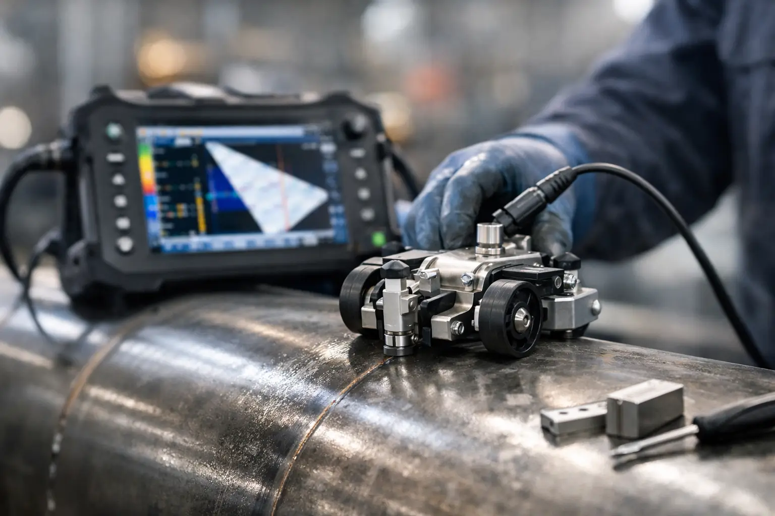

A scan can look clean, show credible indications and still be wrong by several millimetres along the weld. That is the practical risk PAUT encoder calibration is intended to control. If the encoder scale does not match the scanner’s actual travel, every length, position and mapped indication based on that axis becomes questionable.
For field inspection, encoder calibration is not an admin step to rush through before collecting data. It is the link between physical scanner movement and the encoded position reported by the instrument. Get it right and the data is traceable to a real location on the component. Get it wrong and technicians can lose time relocating calls, produce inaccurate length measurements, or repeat a scan that should have been accepted the first time.
What PAUT encoder calibration actually sets
An encoder produces a defined number of pulses as a wheel, belt, chain or carriage moves. The PAUT instrument converts those pulses into distance using a scale factor, commonly expressed as pulses per millimetre or millimetres per pulse. Calibration establishes that relationship against a known physical travel.
The principle is simple: move the scanner a measured distance, compare the instrument’s reported travel with the reference distance, then adjust the encoder scale factor if required. In practice, the quality of the result depends on much more than the maths. Wheel contact, scanner alignment, cable condition, surface profile, drive direction and the reference used all affect whether the calibration holds on the job.
Encoder calibration is separate from wedge delay, sensitivity, index offset and probe position calibration. All are necessary for dependable PAUT data, but they answer different questions. Wedge and probe settings help establish where the sound beam is. Encoder calibration establishes where the scanner was when each A-scan was acquired.
Start with the scan plan, not the menu
Before entering values into the instrument, confirm what the encoder axis represents. On a manual weld scanner, it may be the travel direction along the weld. On a corrosion scanner, it may be the primary raster axis. A pipe scanner may encode circumference, axial travel, or both. Confusion here creates a common problem: an apparently calibrated encoder assigned to the wrong axis or moving in the wrong direction.
The scan plan should state the required encoded axes, scan direction, start reference, index increment and reporting coordinates. This matters when data will be reviewed by another technician or compared with a previous inspection. A position labelled 850 mm from datum is only useful if everyone is working from the same datum and travel convention.
Also confirm the acquisition resolution is realistic. A very fine sampling increment may create large files and slow scanning without improving the decision being made. Too coarse an increment can reduce positional confidence and make short indications harder to define. The appropriate value depends on the procedure, beam coverage, expected flaw type and reporting requirement.
Use a reference that reflects the job
The best calibration reference is a known, stable distance that is longer than the small movements likely to hide error. A short ruler check can confirm that the encoder is alive, but it may not reveal cumulative scale error. Where practical, calibrate over a representative travel length and verify over a second length.
For straight weld scanning, a marked calibration bar, steel rule or prepared plate with clear reference points is usually suitable. The scanner should sit on the same type of surface and use the same wheel arrangement intended for inspection. If a scanner is calibrated on smooth plate then used on a rough, coated or curved surface, the result may not transfer.
Pipe work needs additional thought. A wheel travelling around a pipe can be affected by curvature, inconsistent contact and changes in clamping force. If the inspection is circumferential, verify the encoder using the scanner installed on a representative diameter where possible. A nominal wheel circumference is useful for an initial setup, but it is not a replacement for checking actual travel under working conditions.
A practical calibration routine
A repeatable routine makes encoder checks quicker and easier to defend. The exact screens vary between PAUT instruments, but the field process remains much the same.
- Inspect the scanner before calibration. Check the encoder wheel or drive mechanism for wear, contamination, flat spots and free movement. Confirm the cable is properly seated and strain relieved.
- Set the scanner on the reference surface with normal probe loading and the same configuration planned for the scan. Lock any guides, arms or clamps that will be locked during acquisition.
- Zero the displayed position at a clear physical datum. Avoid vague marks or tape edges that can be interpreted differently by different operators.
- Move the scanner steadily to the second reference mark. Do not drag it sideways, lift a wheel, or reverse direction halfway through unless the procedure specifically calls for it.
- Compare displayed travel with the known reference distance. Adjust the scale factor through the instrument’s encoder calibration function or enter the calculated value required by the procedure.
- Return to the datum, repeat the travel, then verify over another distance. Check both the displayed distance and direction of travel.
The verification pass matters. A calibration value can appear correct after adjustment simply because the same movement was used to set it. Repeating the test, preferably over a different distance, gives far more confidence that the encoder is tracking rather than merely fitting one result.
Check direction, repeatability and backlash
Distance alone is not the whole story. A reversed encoder direction can place data on the wrong side of the start datum. This is usually obvious on the acquisition display, but it is worth confirming before a full scan begins. Move the scanner in the planned positive direction and make sure the displayed coordinate increases as expected.
Then check repeatability. Move from zero to a reference point several times and observe whether the encoder returns to the same reported position. Variation can point to wheel slip, loose mounting hardware, damaged encoder bearings, cable faults or a drive system with backlash.
Backlash is particularly relevant on chain, belt and geared scanner arrangements. If the carriage is moved forward, reversed, then moved forward again, lost motion can create a positional discrepancy before the encoder properly registers travel. For encoded acquisition, avoid unnecessary reversals. If a reversal is unavoidable, follow the scanner and instrument procedure for taking up backlash before recording data.
Why calibration can drift during a shift
Encoder calibration is not always a once-per-job event. Field conditions change. Abrasive scale can coat a wheel, couplant can reduce traction, a guide can loosen, or a wheel can pass over a high weld cap and lose contact. On a long scan, even small slippage becomes a meaningful position error.
Recheck calibration after a scanner is reconfigured, dropped, transported between work fronts, or fitted with a different wheel or carriage. It is also sensible to verify after scanning a difficult surface, especially if the reported travel does not agree with the physical component dimensions.
The same applies when swapping encoders between scanners. Even when connectors and pulse counts match, the effective travel can change with wheel diameter, mounting geometry and contact pressure. A modular equipment setup saves rebuild time, but each purpose-built configuration should be treated as its own calibrated system.
Common causes of poor encoded data
Most encoder problems are mechanical rather than electronic. A worn rubber wheel, inconsistent pressure or a scanner that is not properly guided can create more error than an incorrectly entered pulse count. On painted or scaled surfaces, a wheel may roll across material that is not representative of the parent surface. On narrow components, the scanner may rock enough to alter contact.
Another frequent issue is calibrating with no probe load, then scanning with wedges, probes and cable drag applied. Added load can alter wheel contact or carriage movement. Set up the scanner as it will actually run, including the probe assembly and cable routing.
Cable management deserves attention as well. A heavy or snagged lead can pull a lightweight scanner off line, particularly during manual raster scanning. Keep enough slack for the planned travel, secure the cable where appropriate, and make sure it does not rub against the encoder wheel or interfere with the carriage.
Record enough to prove the result
A useful calibration record does not need to be complicated. It should identify the scanner, encoder, instrument, scan axis, reference distance, measured or displayed travel, final scale factor, date and technician. Include the relevant procedure and any conditions likely to affect repeatability, such as pipe diameter or surface coating.
For critical work, record the pre-scan and post-scan verification. If the end check differs materially from the starting result, assess the data before reporting it. The correct response depends on the amount of error, the procedure tolerance, scan length and whether indications must be relocated or sized. It may mean applying a documented assessment, rescanning the affected area, or investigating the scanner before further use.
PAUT.Tech designs scanning hardware around the reality that technicians need equipment configured for the job, not endlessly rebuilt between unrelated tasks. That same practical approach applies to encoder control: calibrate the complete scanning arrangement, verify it under real contact conditions, and recheck it whenever the setup changes.
A few measured minutes at the start of a scan can prevent hours spent defending coordinates later. When the scanner movement is trustworthy, the inspection team can focus on the indications that matter rather than questioning where the data came from.