
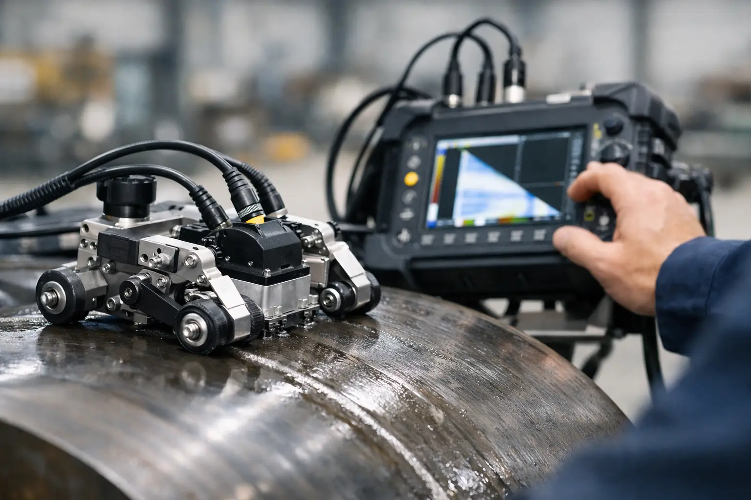

A PAUT scan can go off the rails long before the first A-scan appears on screen. Most of the trouble starts in the mechanical setup - poor wheel contact, the wrong wedge position, encoder slip, cable drag, or a scanner that technically fits the job but fights you the whole way. If you want to know how to set up PAUT scanners properly, start with the physical realities of the inspection, not the software menu.
The right setup depends on what you are scanning. A circumferential weld on small pipe has different demands to a long seam weld on plate, and both are different again from encoded corrosion mapping. That sounds obvious, but plenty of wasted time comes from trying to force one scanner arrangement across every job. In the field, fit-for-purpose usually beats universal.
Start with the inspection task, not the scanner
Before you bolt anything together, define the inspection variables that actually matter. Material, diameter, wall thickness, weld cap condition, coating, scan length, access constraints and reporting requirements all affect scanner setup. Probe count and wedge style matter too, but they only make sense once the job is clear.
For welds, the main question is whether you need stable, repeatable encoded movement along a known scan axis while holding probe position relative to the weld centreline. For corrosion work, you are usually chasing area coverage, indexing accuracy and steady couplant management over a surface that may not be especially friendly. The scanner should support that outcome with the least compromise.
This is also where experienced techs save money. Instead of rebuilding one expensive scanner every second day, it often makes more sense to keep separate setups ready for common jobs. That reduces wear, rebuild time and the chance of introducing setup errors between projects.
How to set up PAUT scanners for stable mechanics
Mechanical stability comes first because bad mechanics create bad data. No amount of gain adjustment will fix an encoder that slips or a probe holder that creeps during a scan.
Start by checking the scanner frame suits the geometry. On pipe, wheel spacing and frame width need to match the diameter range so the scanner sits square and tracks cleanly. On flat work, make sure the wheelbase is long enough to avoid rocking, especially over weld caps or rough coatings. If the scanner is unstable when dry-running over the surface, it will not improve once cables and couplant are added.
Probe holders should be locked firmly but still allow fine adjustment. The common mistake is clamping everything hard before confirming wedge alignment and travel path. Set the scanner on the component, position the probes where they need to run, then tighten in stages. That keeps the assembly true instead of twisting it into place.
Cable management matters more than many setups allow for. Heavy or poorly routed probe and encoder cables can pull a lightweight scanner off line, especially on verticals or around circumference scans. Give the cables enough slack to move freely, but not so much that they drag or snag. A tidy cable path is part of scan accuracy.
Probe and wedge positioning
Once the frame is mechanically sound, set the probes and wedges to suit the inspection plan. This is where precision matters. A scanner can roll beautifully and still collect poor data if the wedges are offset, skewed or sitting at inconsistent pressure.
For weld scanning, establish the correct probe offset from the weld centreline and confirm both sides are mirrored properly where applicable. If you are running dual probes or a combined PAUT and ToFD arrangement, check there is no interference between holders, wedges or cable exits through the full scan length. The setup should travel without one component nudging another out of position.
Wedge contact needs special attention on curved surfaces. A wedge that only partly seats on pipe can produce inconsistent coupling and unstable sound entry. Sometimes the answer is a different wedge profile or a dedicated holder arrangement rather than trying to shim a poor fit. For field work, simple and repeatable usually wins.
Pressure should be enough to maintain contact without creating excess drag. Too light and you lose coupling. Too heavy and you increase wear, fight the movement and risk skewing the scanner. There is no magic number here - it depends on surface condition, wheel type, wedge face and scan orientation.
Encoder setup is not a small detail
If your encoded position is wrong, the rest of the dataset is built on a bad foundation. That is why encoder setup deserves the same attention as probe positioning.
First, make sure the encoder wheel is actually driving on the surface with consistent contact. If it is barely touching, bouncing over profile changes or sharing load poorly with the main wheels, expect slip. On some jobs, the scanner tracks well but the encoder performance is still poor because the wheel is running on scale, spatter or a coating edge.
Then verify direction and distance. A quick encoder check over a known travel length should be standard practice, not an optional extra. If the displayed distance does not match the real travel, sort it before calibration and scanning. Small scale errors become big reporting problems over long runs.
Pay attention to mounting stiffness as well. Any flex in the encoder bracket can introduce inconsistency, particularly on uneven surfaces. A rigid mount with reliable wheel pressure is worth more than a fancy feature list.
Practical checks before calibration
Before you move into instrument calibration, do a dry run with the full scanner assembly. Push or pull it over the actual component, or something close to it, and watch for the basic faults that ruin production scanning.
Look for wheel lift, side drift, cable snagging, wedge chatter and changes in probe pressure through the travel. Check whether the scanner clears clamps, cap profile, supports and nearby obstructions. If the scan path is awkward, fix the mechanics now rather than trying to work around it during acquisition.
This is also the time to confirm access for couplant application. Some scanner layouts look neat on the bench but make it hard to keep the wedges wet once you are on a ladder, on a vessel shell or leaning around pipework. A good setup is one you can actually operate consistently in site conditions.
How to set up PAUT scanners for repeatable field use
Repeatability matters just as much as initial setup. A scanner that takes 40 minutes to build and another 20 minutes to fine-tune might be acceptable in a workshop, but it is a liability on shutdown work or remote callouts.
Build your setup so the critical positions are easy to reproduce. That means using clear probe holder reference points, known wheel spacing, fixed offsets where possible and minimal unnecessary adjustment. Modular hardware helps because you can keep common configurations ready instead of stripping one assembly back to bare parts after every job.
There is a trade-off here. Highly adjustable scanners cover more scenarios, but they also create more opportunities for user error and slow deployment. Purpose-built or task-specific setups give away some universality, but they are often faster and more reliable in day-to-day inspection work. For many contractors, that is the better bargain.
Common setup mistakes that cost time
Most scanner problems are not dramatic failures. They are small setup errors that gradually erode scan quality or productivity.
One is assuming the scanner is the issue when the real problem is the surface condition. Heavy scale, rough coating edges and weld spatter can upset tracking, coupling and encoder performance. Another is over-tightening everything, which can distort holder alignment or make movement unnecessarily heavy. A third is changing too many variables at once. If the scan behaves badly, isolate the cause - mechanics, wedge contact, cable drag, encoder contact or surface condition.
Another common issue is trying to adapt a scanner past its sensible range. Yes, some hardware can be made to work on a marginal diameter or awkward profile, but that does not mean it should be. If a job comes up regularly, a dedicated arrangement is often the practical answer. That thinking sits behind a lot of modern modular scanner design, including the sort of field-driven hardware approach PAUT.Tech is built around.
Final checks before production scanning
Once the scanner is assembled, aligned and moving properly, lock in the last checks. Confirm probe identity and channel assignment, verify encoder scale and direction again, and make sure all fasteners are secure after the test run. Recheck wedge contact with couplant, especially if the component surface has changed temperature or orientation since the initial setup.
Then mark or note the key mechanical positions. If something gets bumped during the shift, you want a fast path back to the known-good setup. That is not overkill. It is standard discipline when your data quality depends on repeatable geometry.
A good PAUT scanner setup should feel uneventful. It should track properly, couple consistently and give the operator one less thing to fight. That is usually the best sign you have done it right.