
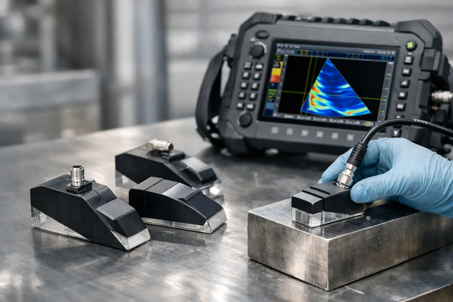

A PAUT probe can be perfectly capable on paper and still produce poor coverage if the wedge is wrong. Knowing how to select PAUT wedges starts with the inspection requirement, not with the wedge catalogue. The wedge must put the beam into the component at the right angle, from a repeatable reference point, while maintaining coupling and physical access on the actual job.
For weld inspections, that means considering the weld preparation, cap profile, parent material thickness and scan surface before choosing an angle or footprint. For corrosion work, the priority may be a stable contact face over a changing surface profile. A wedge that is convenient to mount but does not support the required sound path is not a practical solution.
Start with the inspection procedure
The qualified procedure should drive wedge selection wherever one exists. It defines the inspection volume, required beam angles, scan plan, calibration requirements and acceptance criteria. Select a wedge that allows the probe to achieve those requirements without forcing compromises in coverage or calibration.
When developing a procedure, work backwards from the area that must be interrogated. Consider whether the target is a weld root, sidewall, cap region, heat-affected zone, planar cracking or general wall loss. Then determine which wave mode and refracted angles provide useful coverage of that area.
A common mistake is selecting a familiar 45, 55 or 60 degree wedge before confirming whether that angle actually reaches the feature of interest. A 60 degree shear-wave setup may give strong root coverage on one weld configuration, while a 45 degree setup may better suit another thickness, bevel geometry or access restriction. There is no universal best wedge angle.
Match the wedge to the probe first
A PAUT wedge is a mechanical and acoustic interface designed for a specific probe family. It needs to match the probe footprint, element orientation, pitch, active aperture and fixing arrangement. Small differences matter. A wedge intended for a different array can shift the effective index point, alter the beam exit position or prevent the probe from seating correctly.
Confirm the probe's element count, pitch, active aperture range and intended orientation before ordering or machining a wedge. Linear arrays, especially, may be mounted for transverse or longitudinal scanning depending on the application. The wedge needs to support the planned scan direction and beam steering range.
The wedge also needs enough physical length for the selected aperture and steering limits. If the beam is steered too far towards a wedge edge, internal reflections, signal loss and distorted beam profiles can follow. A setup may look acceptable during a quick calibration but become inconsistent once scanning begins.
Select the refracted angle for useful coverage
The wedge angle creates a nominal refracted angle in the test material, but the final beam behaviour depends on the wedge material, component material and the selected focal laws. This is why a wedge described simply as “55 degree” is not enough information on its own.
For carbon steel welds, shear-wave wedges are commonly used to generate a sectorial scan that covers the root, fusion faces and cap-side regions. The nominal angle should sit within the useful range defined by the procedure, while allowing steering without creating impractical skips or excessive mode conversion.
Higher refracted angles can improve sensitivity to some planar flaws and provide better access to near-surface regions from one side of a weld. They can also produce longer sound paths, more attenuation and less tolerance for poor coupling. Lower angles may provide more direct coverage through thicker sections but can leave geometric blind areas depending on the weld profile.
For austenitic materials, dissimilar-metal welds, cladding or coarse-grained material, the decision is more involved. Beam skewing, attenuation and anisotropy can make standard carbon-steel assumptions unreliable. Wedge selection should be validated using representative reference blocks and the actual inspection procedure rather than relying on a nominal angle alone.
Check the index point and beam exit position
The probe index point is central to accurate weld positioning. It is the reference used to relate beam path, skip distance and indication location to the weld centreline. The wedge design must provide a stable, identifiable index point that can be calibrated and repeated in the field.
A worn wedge can move the effective index point and change the refracted angle. On a critical weld job, that affects more than image quality. It can make scan positions, encoded data and reported locations unreliable. Verify the index point and angle during calibration, and recheck them whenever the wedge shows meaningful wear or damage.
Choose a contact face that suits the component
Flat wedges belong on flat, reasonably smooth scan surfaces. Trying to run one over pipe, a heavily crowned weld cap or an uneven coated surface usually leads to variable coupling and encoder slip. That variation can appear as amplitude changes, missing data or false geometry in the scan image.
For pipe and other curved components, use a wedge with a radius that matches the outside diameter as closely as practical. A correctly radiused contact face improves coupling stability and helps keep the beam position consistent around the circumference. For small-diameter pipe, this becomes especially important because a flat contact face only touches along a narrow line.
The scan surface condition also matters. Loose scale, weld spatter, sharp cap edges and damaged coating can rapidly wear a wedge or stop it tracking properly. Surface preparation is often the cheapest way to improve a PAUT setup. Remove what can be removed, then choose a wedge profile that can maintain contact without excessive force.
Low-profile wedges can help where clearance is limited around attachments, supports or adjacent components. The trade-off is that a reduced body may limit steering range, aperture size or mechanical stiffness. Check the full scanner and probe assembly, not just the wedge, against the available access.
Consider wedge material and job conditions
Most PAUT wedges are manufactured from materials selected for consistent acoustic velocity, wear resistance and machinability. Their performance still changes with temperature. A wedge calibrated in a cool workshop may not retain the same delay, angle or coupling behaviour on hot pipework in the field.
If the component is hot, confirm the permitted operating temperature for the probe, wedge, cable and couplant as a complete system. Do not assume a high-temperature couplant makes a standard wedge suitable for hot inspection. Heat can affect wedge dimensions, acoustic properties and probe bonding.
Chemical exposure, abrasive surfaces and long production scans also influence wedge life. A harder, more wear-resistant contact face may be worth it on rough fabrication work, while a softer material can sometimes offer better conformity on less demanding surfaces. The sensible choice depends on how often the wedge will be used and what replacing it costs in downtime as well as dollars.
Design for scanning, not just calibration
A wedge can calibrate well on a block and still be awkward in production. Before committing to a setup, consider how the probe will be carried across the component. Will it sit securely in the scanner? Is there enough clearance for the cable? Can the operator maintain couplant ahead of the wedge? Does the scan direction keep the index point where the procedure expects it?
For encoded inspections, mechanical repeatability matters as much as the sound beam. The wedge should sit firmly in its holder without rocking, and the probe-wedge assembly should track consistently relative to the encoder. A loose or poorly supported assembly creates position error that cannot be repaired later in the analysis software.
This is where task-specific accessories are useful. A scanner, holder and wedge designed around the same inspection geometry reduce rebuild time and remove avoidable alignment issues. PAUT.Tech focuses on practical hardware combinations because field teams need equipment that can be deployed for the job, not endlessly reconfigured between jobs.
Validate every wedge before production scanning
Treat a new wedge as a setup component that requires verification, not a finished answer. Calibrate wedge delay, index point and refracted angle using the method required by the procedure. Confirm sensitivity and coverage on a suitable reference block, then review the scan plan for blind zones, excessive skips and near-surface limitations.
During scanning, watch for signs that the wedge is no longer performing consistently: changing backwall response, unstable couplant noise, uneven amplitude across the scan, visible contact-face wear or a shift in calibration checks. A quick recalibration check can prevent a large amount of data from needing to be rescanned.
The right PAUT wedge is the one that gives the required beam coverage, repeatable positioning and workable access on the component in front of you. Select it around the procedure and scan mechanics, then verify it under real conditions before relying on the data.