
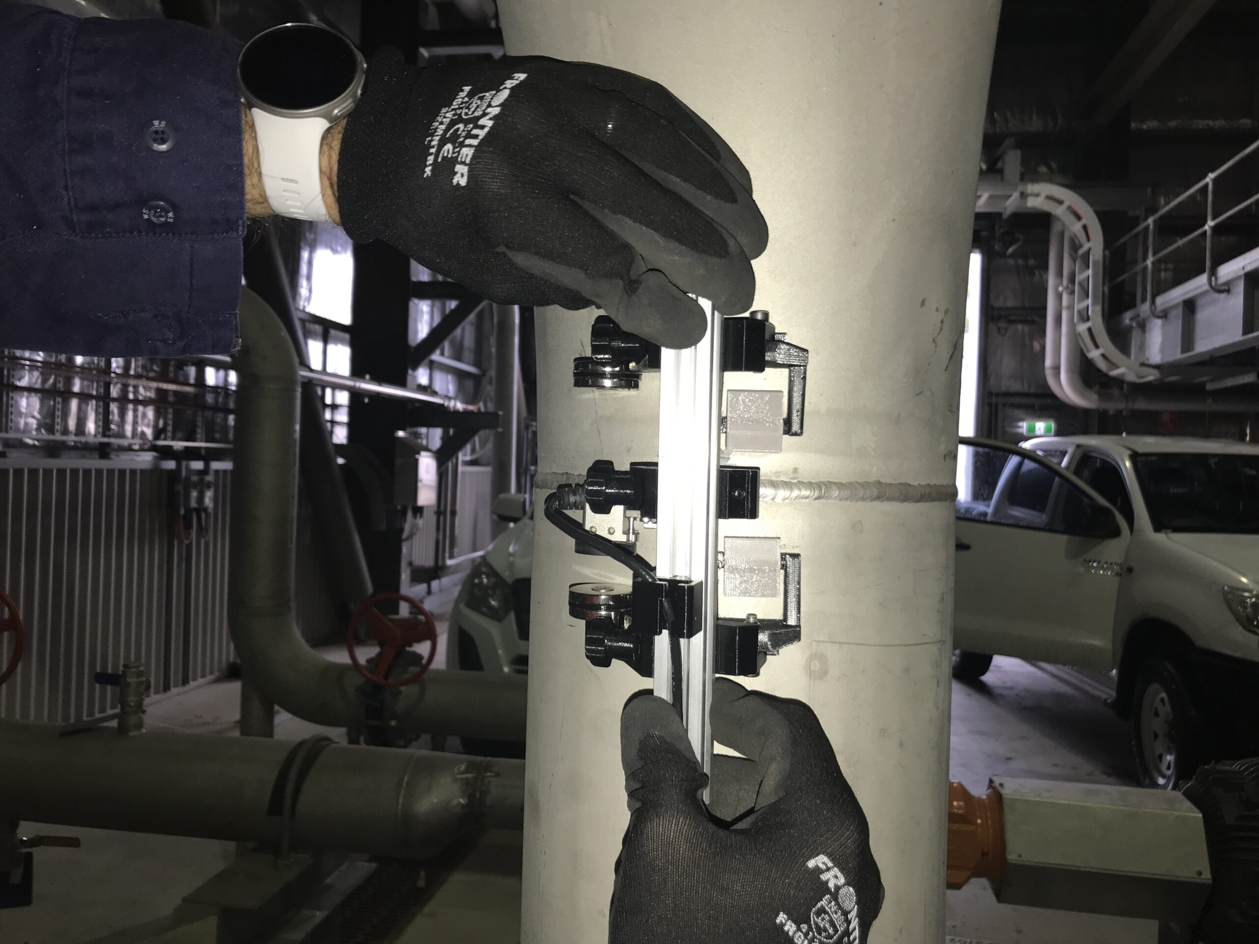

A poor encoder choice can turn a sound scan plan into a difficult day on site. Lost counts, wheel slip, unsuitable mounting or a cable that does not suit the instrument can compromise encoded PAUT or ToFD data before the inspection has properly started. Knowing how to choose an NDT encoder means looking beyond the pulse count on a data sheet and matching the encoder to the scanner, surface, procedure and working conditions.
For most field work, the right answer is not the highest-resolution encoder available. It is the encoder that delivers repeatable position data with the least setup time and the fewest opportunities for operator error.
Start with the inspection movement
An NDT encoder measures travel. Before comparing models, define exactly what is moving and how that movement will be controlled. A pipe scanner travelling circumferentially has different requirements from a manual weld scanner travelling along a plate, and both differ from a corrosion mapping frame covering a large area.
Ask whether the encoder will measure linear travel, rotational travel or both. A single-axis encoder may be sufficient for a conventional encoded weld scan where the probe position is fixed relative to the scanner. A two-axis arrangement is generally needed when recording a raster pattern for corrosion mapping, encoded manual scanning or other inspections where both scan and index positions matter.
Also consider whether travel is continuous and guided. An encoder wheel running on a straight, clean plate has an easy job. The same wheel crossing weld caps, scale, surface coating, small-radius pipe or uneven geometry can slip or bounce. In those conditions, a practical mounting arrangement and good wheel contact matter more than chasing very fine nominal resolution.
How to choose an NDT encoder by resolution
Encoder resolution is usually discussed as pulses per revolution, counts per revolution or distance per count. These figures are related, but they are not interchangeable without considering the drive wheel diameter and the instrument's quadrature decoding.
For a wheel encoder, the basic relationship is straightforward: wheel circumference divided by usable counts gives the distance represented by each count. A smaller wheel can provide finer distance resolution for the same encoder, but it may be more affected by surface irregularities. A larger wheel bridges rougher surfaces more easily, but produces less resolution unless encoder count increases accordingly.
The useful question is not, “What is the finest resolution I can get?” It is, “What resolution does the inspection procedure and acquisition plan require?” If the encoded increment is already finer than the beam spacing, aperture step or reporting requirement, further encoder resolution may provide no useful inspection benefit. It can simply create more data, slower setup and a greater sensitivity to minor wheel movement.
For PAUT weld inspection, choose a resolution that supports the required scan increment and positional accuracy across the weld volume. For ToFD, stable and repeatable travel is especially important because positional inconsistency can affect how indications are represented and located. For corrosion mapping, the encoder increment needs to align sensibly with probe footprint, scan plan and the level of coverage required.
Do not overlook direction. Most encoded applications need quadrature output so the instrument can recognise forward and reverse movement. Confirm that the chosen encoder and acquisition unit use compatible signal logic, voltage levels and channel configuration.
Check instrument and cable compatibility first
An encoder is only useful if it communicates correctly with the ultrasonic instrument. This is where apparently simple purchases can become time-consuming.
Confirm the instrument's encoder input type, connector style, pinout, channel requirement and expected signal format before selecting hardware. Check whether it accepts incremental quadrature signals, whether it needs one or two channels, and whether the software requires a particular setup for counts, direction or axis assignment.
Cable selection deserves the same attention. A cable can be electrically correct but operationally wrong if it is too short for the scanner arrangement, too stiff around a small pipe scanner, or prone to strain at the connector. Field setups commonly involve scanner extensions, awkward access, elevated work and frequent pack-down. Choose a cable length and exit direction that do not pull on the encoder or interfere with travel.
If your business runs more than one instrument platform, standardising connectors and cable arrangements where possible reduces setup errors. Label encoder cables clearly and keep a tested spare in the kit. A damaged encoder lead can look like an instrument fault, a scanner fault or an acquisition problem until time has already been lost.
Match the mounting method to the scanner
The encoder needs a rigid, repeatable relationship with the scanner and probe position. If the mounting point flexes, shifts or requires constant adjustment, the positional information will not reliably represent the probe location.
Purpose-built scanner mounts are usually preferable to improvised brackets. They make it easier to set wheel pressure, maintain alignment and remove or replace the encoder without rebuilding the whole scanner. This is particularly valuable for service companies moving between weld inspection, pipe work and corrosion jobs. A dedicated scanner with an encoder already fitted is often faster to deploy than one premium scanner that has to be reconfigured for every task.
Look closely at access around the scan path. On a small-diameter pipe, the encoder body, cable and mounting bracket may compete for space with probe holders, chains, guide bands and the weld itself. On plate scanning, the concern may be whether the wheel stays in clean contact without crossing the weld cap or catching on a transition.
For removable scanner systems, repeatability matters after transport. The operator should be able to fit the encoder, confirm wheel contact and start a verification scan without spending half an hour finding the same position again.
Consider the surface, not just the component
The nominal component material does not tell the whole story. Surface condition drives encoder performance. Painted steel, heavy scale, blasted surfaces, oily plate, high-temperature material and rough weld profiles all change how a drive wheel behaves.
A rubber or polyurethane wheel may provide useful grip on smooth surfaces, but can wear more quickly on abrasive scale. A harder wheel may last longer yet be more prone to slip. There is no universal best material. The decision depends on the actual work mix and whether consumable wheels are readily replaced.
Wheel loading is another trade-off. Too little contact pressure can cause lost travel and erratic counts. Too much pressure can increase drag, wear the wheel, affect manual scanner movement or allow a light scanner to skew. The best setup has enough consistent contact to prevent slip without making the scanner difficult to operate.
Where scan accuracy is critical, verify the encoder on the job surface rather than relying on a bench check. Mark a known travel distance, move the scanner through it under normal working pressure, and compare reported travel with the physical measurement. Repeat in both directions. This quick check can reveal slip, backlash, incorrect scaling or an axis-direction error before acquisition begins.
Build durability into the decision
NDT hardware is regularly carried through workshops, site compounds, plant areas and confined access routes. An encoder that performs well on a clean bench but has exposed bearings, vulnerable connectors or an awkward cable exit may not suit field work.
Prioritise a protected housing, sensible strain relief and a mounting arrangement that shields the encoder from knocks. Consider how easily the wheel, cable or encoder body can be replaced if damaged. For owner-operators and small inspection teams, repairability is often more useful than a highly specialised assembly that must be sent away for a minor failure.
It is also worth separating the encoder from the scanner decision where possible. Modular hardware lets you keep suitable encoders with different task-specific scanners rather than making one setup do every job. That approach can reduce rebuild time, limit wear and keep more equipment available when several inspections are running at once.
Use a practical pre-purchase check
Before committing, run through four points: the required scan increment, instrument compatibility, scanner mounting arrangement and expected surface condition. If any of these is unclear, the encoder specification is not yet complete.
Then consider the operating reality. Will the technician be scanning in a fabrication shop, on a pipe rack, on a ute tray between call-outs, or in a shutdown where replacement parts are not close by? A slightly simpler encoder that mounts quickly and stays reliable may be the better commercial choice than a more complex option with capability the job never uses.
PAUT.Tech approaches scanner hardware on that basis: fit-for-purpose components that can be deployed for the work in front of you, without turning every inspection into a rebuild project.
A well-chosen NDT encoder should disappear into the process. Once its scaling is verified and its wheel stays in contact, the technician should be able to focus on probe placement, coverage and data quality - the parts of the inspection that actually decide the outcome.