
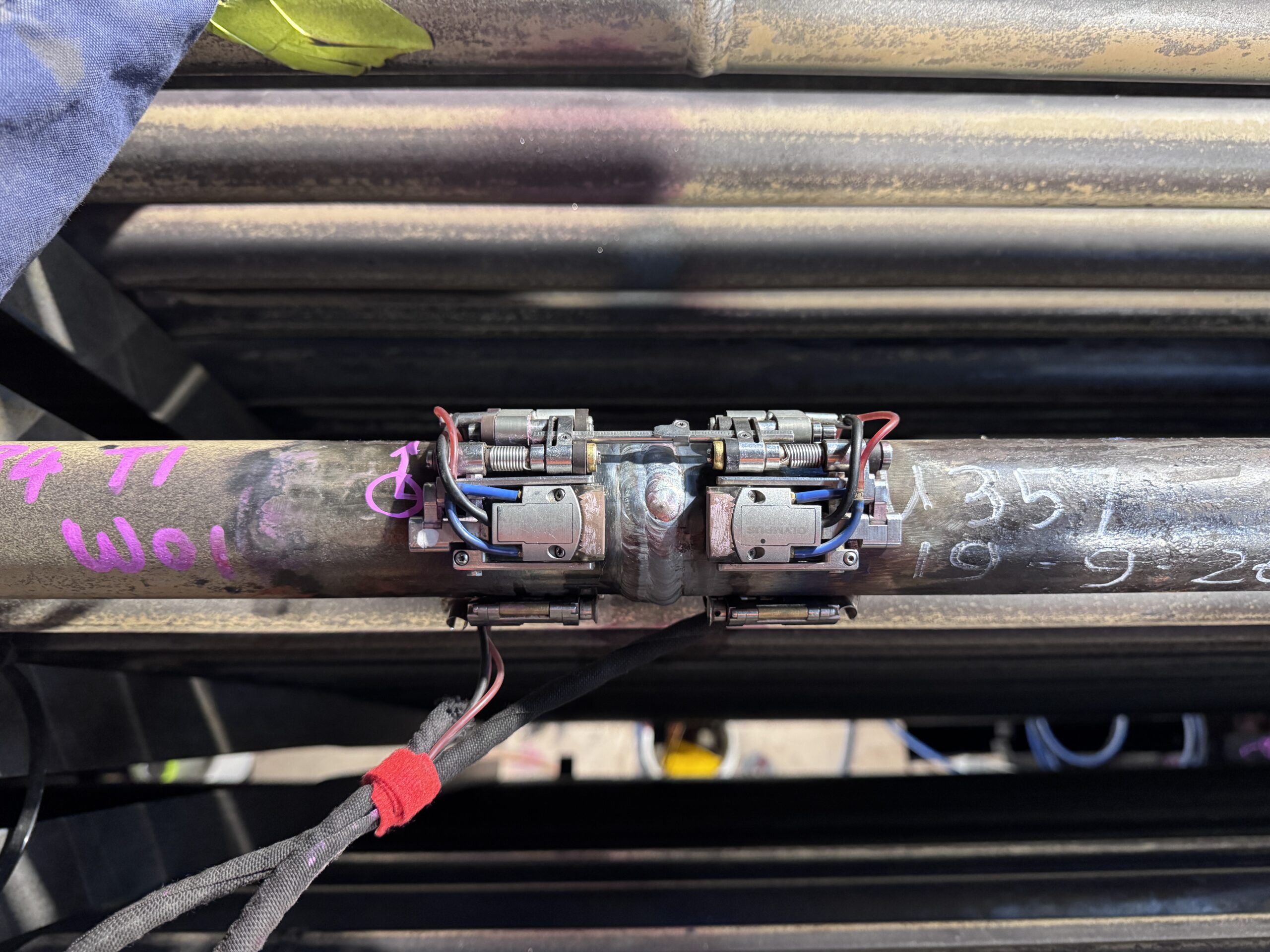

A PAUT scan can look clean, repeatable and well encoded while still being wrong. Wedge alignment for PAUT inspection is where the mechanical setup, focal law assumptions and actual weld geometry meet. If those three do not agree, the result may be incomplete coverage, incorrect position reporting or an indication that cannot be sized with confidence.
This is not just a calibration task completed at the start of a shift. Wedge alignment needs to be treated as part of every inspection setup, particularly when changing probes, wedges, scanner frames, weld configurations or materials. A few minutes spent checking alignment is usually cheaper than explaining a rescan after the job has moved on.
Why wedge alignment affects every PAUT result
A PAUT wedge determines how ultrasonic energy enters the component. Its geometry establishes the probe position relative to the scan surface, the nominal refracted angle, the direction of the sound path and, in many setups, the reference point used to locate data against the weld.
The focal laws may be correct for the probe and wedge combination entered into the instrument, but they cannot compensate for a wedge that is physically sitting off-axis, poorly seated or configured with the wrong reference values. The beam can then miss the intended fusion face, strike the weld at an unintended angle or report an indication at the wrong distance from centreline.
The consequence depends on the inspection. On a simple butt weld with generous scan coverage, a small error may only reduce sizing confidence. On a narrow-groove weld, a thick-wall component or a scan with limited access, the same error can leave a critical zone unexamined. Misalignment is especially costly when it creates a believable image that appears to show complete coverage.
There are two parts to the problem. Instrument calibration establishes the ultrasonic model - wedge delay, index point, refracted angle and sensitivity response. Mechanical alignment establishes whether that calibrated model is being applied to the actual weld in the intended direction. Both need to hold up.
Start with the correct probe and wedge pairing
A wedge is not a generic mounting block. It is part of the ultrasonic system. The probe model, element pitch, aperture, wedge material, wedge angle and roof angle all influence the focal law calculation and beam behaviour.
Before fitting the probe, confirm that the selected wedge is intended for that probe footprint and frequency range. A wedge that appears to fit mechanically can still place the active aperture in the wrong location or produce beam characteristics outside the values used in the procedure. Check the wedge identification against the instrument setup rather than relying on appearance alone.
Inspect the contact surface as well. Wear, scratches, embedded grit and local deformation can affect coupling and alter how the wedge sits on the component. This matters most on narrow contact faces, small diameters and painted or rough surfaces. A worn wedge does not always fail dramatically. More often, it introduces variable coupling and a subtle positional error that is difficult to recognise once scanning has begun.
If the wedge has a contoured surface, verify the component diameter and curvature match the wedge design. For pipe work, a wedge intended for one outside diameter range may rock or bridge on another. The operator may be able to maintain coupling with extra gel, but that does not mean the probe is aligned consistently.
Establish a reliable weld reference
Wedge alignment begins with a clear reference to the weld centreline. Marking the centreline and toe locations is still one of the most effective field controls available. It gives the technician a physical check against the scan plan and makes it easier to confirm that the scanner is travelling where the encoded data says it is.
Where possible, use both weld toes to establish the centreline rather than assuming the cap is symmetrical. A weld cap can be offset from the root, and cap width alone is not always a dependable guide to the actual joint preparation. If drawings, procedure details or access to the reverse side are available, use them to build a more defensible reference.
For encoded scanning, the scanner should be positioned so its travel axis remains parallel to the intended reference. A skewed scanner changes the relationship between encoder position and the weld. The result is often a gradual drift in displayed position across the scan length. That can make side-drilled holes or known reflectors appear displaced and can complicate correlation with visual findings or repair locations.
Align the probe axis, not just the scanner frame
A scanner can be square to the weld while the probe carriage is not. Check the actual probe axis and wedge orientation against the scan direction. This is particularly relevant on modular scanner systems, where a carriage, probe holder or adapter can introduce a small angular offset.
For a linear scan across a butt weld, the probe should be aligned to produce the skew angle specified in the procedure. For a zero-degree skew setup, that means the probe axis is normal to the weld centreline. For a deliberate skew scan, set and record the intended angle rather than estimating it by eye.
Small errors in skew can matter. A beam that is rotated relative to the planned plane changes its interaction with bevel faces and planar defects. It can reduce response from lack of fusion, distort the apparent orientation of an indication and affect the validity of sizing techniques that assume a known beam plane.
Calibrate, then verify on the job geometry
Wedge delay and index point calibration should be completed using suitable reference reflectors and in line with the governing procedure. The key point is that calibration establishes values for the wedge and probe as they are being used, not values copied from a previous setup.
Refracted angle verification is equally important. Nominal wedge markings are a starting point, not proof of the angle achieved in the test material. Material velocity variation, wedge condition and setup selection can all influence the outcome. If the inspection relies on a specific angle to target a fusion face or root region, verify it rather than assuming it.
After calibration, use a practical check that resembles the inspection geometry where possible. Known reflectors in a representative block, a reference weld or established geometry can reveal whether the beam is reaching the intended zones. This is also where mechanical alignment issues often become obvious. If the response pattern changes unexpectedly between scan directions or across a short distance, investigate the physical setup before adjusting gain or rejecting the data.
A useful distinction is this: calibration confirms the instrument can calculate the beam path; verification confirms the beam path is useful on the job.
Keep the wedge stable during scanning
Correct alignment at the start is only valuable if it is maintained. Scanner frames need enough stiffness to prevent probe rotation, lift-off or sideways movement as they travel over cap transitions, tack remnants, grinding marks and surface changes. Excessively loose probe holders make repeatable positioning difficult. Excessively tight holders can create drag, uneven coupling or damage to the wedge face.
Couplant should be applied consistently. Too little creates dropouts; too much can allow a wedge to hydroplane or mask poor contact on a smooth surface. On vertical, overhead or hot work, the couplant choice and delivery method become part of alignment control because they affect how steadily the wedge tracks.
Watch the live data while scanning. A sudden change in backwall response, noise level or reference reflector amplitude may indicate coupling loss, but it can also signal wedge movement. Do not assume every signal change is material-related. Stop, inspect the setup and rescan the affected area when there is doubt.
For long welds, repeat key checks at sensible intervals and after any interruption. This includes checking scanner position against centreline markings, confirming encoder direction and zero, and inspecting whether the probe holder has loosened. Field equipment is exposed to vibration, temperature changes and ordinary handling. A setup that was correct at the first metre is not automatically correct at the twentieth.
Common alignment mistakes that create rework
The most common issue is treating the weld cap as the only reference. Another is moving a calibrated probe and wedge assembly to a different scanner without rechecking its axis and offset. These shortcuts are understandable when a job is under pressure, but they disconnect the focal law model from the real scan position.
Technicians also run into trouble when they use a contoured wedge on the wrong diameter, ignore wedge wear, or set up a skew angle without a physical reference. Each can produce data that looks acceptable until it is compared with another technique, another scan direction or the actual repair location.
There is also a trade-off between speed and control. A quick manual setup may be appropriate for a short, accessible examination with generous coverage margins. Encoded weld mapping, critical-service work and restricted access jobs justify more deliberate fixturing and verification. The right level of control depends on the procedure, acceptance standard, component consequence and access available.
Build alignment into the scanner setup
The best scanner arrangement is one that makes correct alignment easy to repeat. Clear probe positioning, stable wedge retention, adjustable offsets and an encoder path that follows the intended reference reduce the chance of operator-dependent variation. Purpose-built scanner hardware is often more productive than repeatedly adapting one frame for every weld, because fewer compromises are being carried into the setup.
PAUT.Tech equipment is designed around that practical reality: use a scanner configuration that suits the inspection rather than spending field time rebuilding a system that was never quite right for the job.
A correctly aligned wedge will not replace a qualified procedure, suitable calibration block or competent interpretation. It does, however, give the rest of the inspection a sound physical foundation. When the beam, wedge, scanner and weld reference agree, the data is easier to trust, easier to report and far less likely to send the crew back for a rescan.